Athletic archive videotape splice inspection is the pre-digitization assessment process that locates every adhesive splice in a legacy game cassette, evaluates the structural integrity of the splicing tape and the tape strand immediately surrounding it, classifies each splice by failure risk, and determines whether the cassette can proceed to digitization or must be routed to a trained conservator for re-splicing before any playback is attempted. A videotape splice is a physical joint — a narrow strip of clear polyester-backed adhesive tape applied across the non-oxide face of two butted tape ends — created to join a broken strand, attach a new section of tape, or edit content during the recording’s original use. In school athletic archives, splices appear on game tapes for three main reasons: a cassette broke during a high-speed rewind on consumer equipment and was repaired by a coach or AV staff member; an editor assembled tournament highlights by splicing segments from multiple cassettes; or a camera operator joined tape from different rolls to extend recording time for a multi-session event. In each case, the splice represents a mechanical discontinuity in the strand — a location where the tape is not a single piece of material but two pieces held together by an adhesive joint whose integrity declines with every decade of storage and every playback cycle.
The consequence of a failed or failing splice in a VHS transport is rarely minor. As the tape travels the helical-scan path — wrapping around the rotating drum, riding against stationary guide posts, and being drawn forward by the capstan and pinch roller — any section with a lifting splice-tape edge presents the guide posts and drum entry with an irregular leading surface. That edge catches, releases, and re-catches on each guide contact, generating a lateral and vertical flutter that shifts the tape’s position relative to the rotating heads and corrupts the captured signal in the frames surrounding the splice. A splice that fully delamdinates during playback converts the cassette from a recoverable recording into two loose tape ends inside the shell — with the former contents of the tape now possibly creased, folded, and jammed around the head drum assembly. A splice that holds through one playback but is never documented may delaminate on the capture deck during an unmonitored overnight digitization run, destroying both the source tape and the beginning of the digital file that was building on the capture workstation.
This guide gives school athletic directors, AV coordinators, IT and facilities staff, and archive volunteers a systematic splice inspection workflow — covering the visual, tactile, and transillumination techniques that locate splices in a wound cassette pack, the stop-work criteria that determine which cassettes must not be threaded without specialist intervention, the documentation format that records splice condition as part of the accession record, and the conservator escalation path for cassettes whose splice condition places them outside the safe-capture threshold.

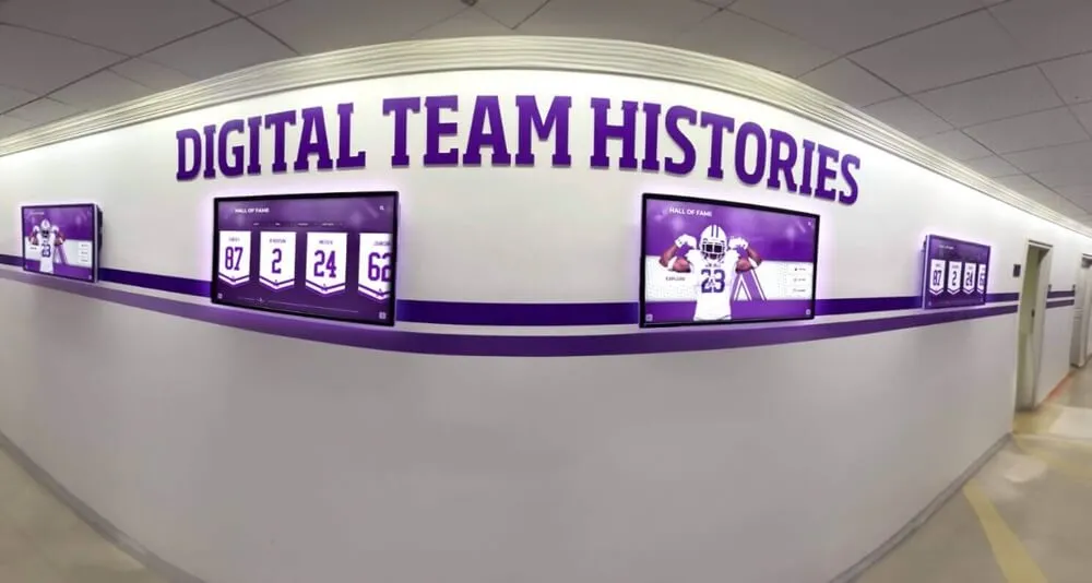
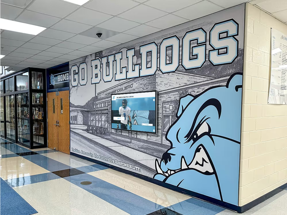
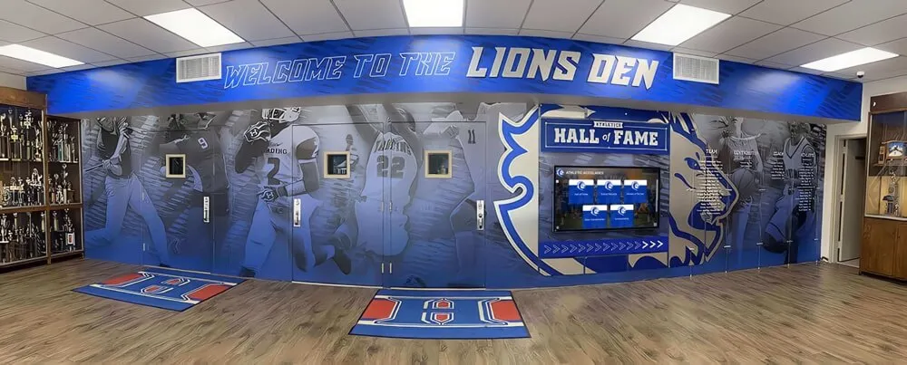
Athletic hallway recognition displays that present decades of program history depend on game footage successfully recovered from legacy VHS cassettes — splice inspection before digitization is the pre-capture step that ensures each cassette reaches the playback deck with its physical integrity confirmed rather than assumed
Why Splices in School Athletic Tapes Require Specific Inspection
The VHS format’s tape transport is mechanically demanding in ways that make splices a particular risk compared with open-reel formats. In open-reel playback, the tape path is relatively direct and the recording head makes gentle linear contact with the tape surface. In VHS, the tape wraps around the rotating drum at a prescribed helix angle — approximately 180 degrees of drum contact — and is maintained at that angle by a sequence of precisely positioned guide posts that control both the tape’s lateral height and its entry and exit angle relative to the drum surface. The drum itself spins at approximately 1,800 rpm (for NTSC), with the video heads sweeping across the tape at a rotational velocity that corresponds to a linear head-to-tape speed of approximately 4.85 m/s — far faster than the tape’s own transport speed of 33.35 mm/s at Standard Play.
This geometry creates three specific failure vectors at any splice point:
Guide-post contact at the splice edge. The stationary guide posts in the tape path contact the tape edges to maintain vertical registration. When the tape carries a splice with a lifting or peeling adhesive edge, that edge contacts the guide-post surface and can fold, tear, or further peel the splice tape on each pass. Consumer guide posts are smooth metal cylinders not designed to accommodate surface protrusions — a lifting splice-tape edge a fraction of a millimeter high is sufficient to initiate catching behavior.
Thickness discontinuity at the drum entry. The splice tape adds a thin layer — typically 0.04–0.06 mm — to the base film at the joint location. As this thicker section enters the drum wrap, it alters the contact angle and the tension distribution in the drum wrap section. In isolation, a well-adhered splice tape on a fresh joint causes only minor disruption. On an aged splice where the adhesive has softened or crystallized, the thickness discontinuity is accompanied by an adhesive release risk at precisely the point of highest mechanical stress.
Delamination under capstan tension. The capstan draws the tape forward against the resistance of the supply reel brake and the tape’s own inertia. The tensioned strand transfers stress across the splice joint with each capstan cycle. A splice whose adhesive has partially released bears the full strand tension across a progressively smaller adhesion area — until the remaining area fails suddenly, separating the two tape ends while the capstan continues to draw one section forward and the supply reel holds the other.
School athletic archive tapes are disproportionately likely to have splices compared with tapes of equivalent age from home recording collections, because game tapes were actively used as coaching tools — rewound, reviewed, copied, and edited — and because coaches working with limited budgets often repaired broken tapes rather than discarding them. An athletic tape labeled “1989 State Championship — Semifinals and Finals” may represent a single cassette assembled from two original recordings by splicing at halftime of the first game, meaning that a splice potentially falls in the middle of the most historically significant footage in the collection.
Splice Types Found in VHS Athletic Archive Collections
Not all splices present the same risk profile. Understanding the splice type visible in a given tape guides the severity assessment and the conservator referral decision.
| Splice Type | Description | Common Origin in School Archives | Risk Level |
|---|---|---|---|
| Diagonal adhesive splice | Cut at approximately 45° to the tape width; splicing tape applied to base side | Professional or semi-professional repair; editing suites used at some schools | Lower — clean diagonal angle reduces abruptness of transport contact |
| Straight (perpendicular) cut splice | Cut straight across the tape width; splicing tape applied to base side | Consumer repair by coaches or AV staff; most common school archive splice type | Moderate — abrupt transition affects video sync at splice point |
| Overlap splice | One tape end overlaps the other before splicing tape is applied | Amateur repair; creates a thick section at the joint | Higher — thickness step at overlap increases drum-entry disruption |
| Double-spliced repair | Two pieces of splicing tape applied at the same joint from successive repair attempts | Failed first splice subsequently patched without full removal of original | High — compounded adhesive layers; higher delamination risk |
| Manufacturer’s factory splice | Thin clear leader or short length of non-oxide tape at cassette start or end | Standard for consumer VHS cassettes at the tape start and end sections | Low — modern adhesive on a section that receives minimal head contact |
| Fully delaminated splice | Splicing tape has released; two ends held only by tape pack tension or by accidental wrapping | Any of the above, after complete adhesive failure | Stop-work — do not thread; route to conservator immediately |
The factory splices at the start and end of a VHS cassette (the clear leader or short non-oxide section that precedes and follows the recorded portion) are generally low-risk because the adhesive was applied to fresh tape in a controlled environment, the joint receives almost no rotating-head contact, and the factory splicing tape is formulated for long-term adhesion. The splices that require inspection attention are those applied in the field during repairs and edits — typically identifiable by misaligned edges, visible splicing-tape width inconsistencies, or the slightly different gloss of consumer splicing tape compared with the surrounding base film.
Step 1: Cassette Shell and Viewing Window Inspection
The first inspection step requires no tape handling — it uses the cassette’s built-in viewing window to assess the wound tape pack before any tape is exposed.
Examining the tape pack edge through the viewing window:
Hold the cassette with the tape-pack side facing a bright, diffuse light source (a desk lamp with a diffusion shade, a light table, or indirect daylight from a window). Tilt the cassette slowly while observing both the supply and take-up reel pack edges through the window. A uniformly wound tape pack appears as a smooth, continuous edge surface — individual tape layers are visible but flush with one another, producing no visible step or offset.
A splice in the wound pack typically appears as one or more of the following:
- A slight step or offset at the tape edge, where one layer is displaced laterally by a fraction of a millimeter relative to its neighbors. The step is caused by the thickness of the splicing tape, which causes the layer at the splice to sit fractionally higher on the hub than the layers above and below it.
- A transverse line of increased brightness crossing the wound tape edge — the splicing tape’s slight reflectivity difference from the base film surface, visible when the light angle is adjusted to rake across the pack surface.
- A visible gap or shadow between two tape layers — the indication that the splice has partially or fully delaminated and the two tape ends are held apart by the wound-pack tension rather than by the adhesive joint.
Document the approximate location of each observed splice in terms of its position in the supply or take-up pack (near the hub, near the outer layers, or in the mid-pack region) and its rough percentage from the tape start. A splice near the outer layers of the supply reel corresponds to a location early in the tape’s content — likely within the first fifteen minutes of a Standard Play recording. A splice in the mid-pack corresponds to the mid-content region.
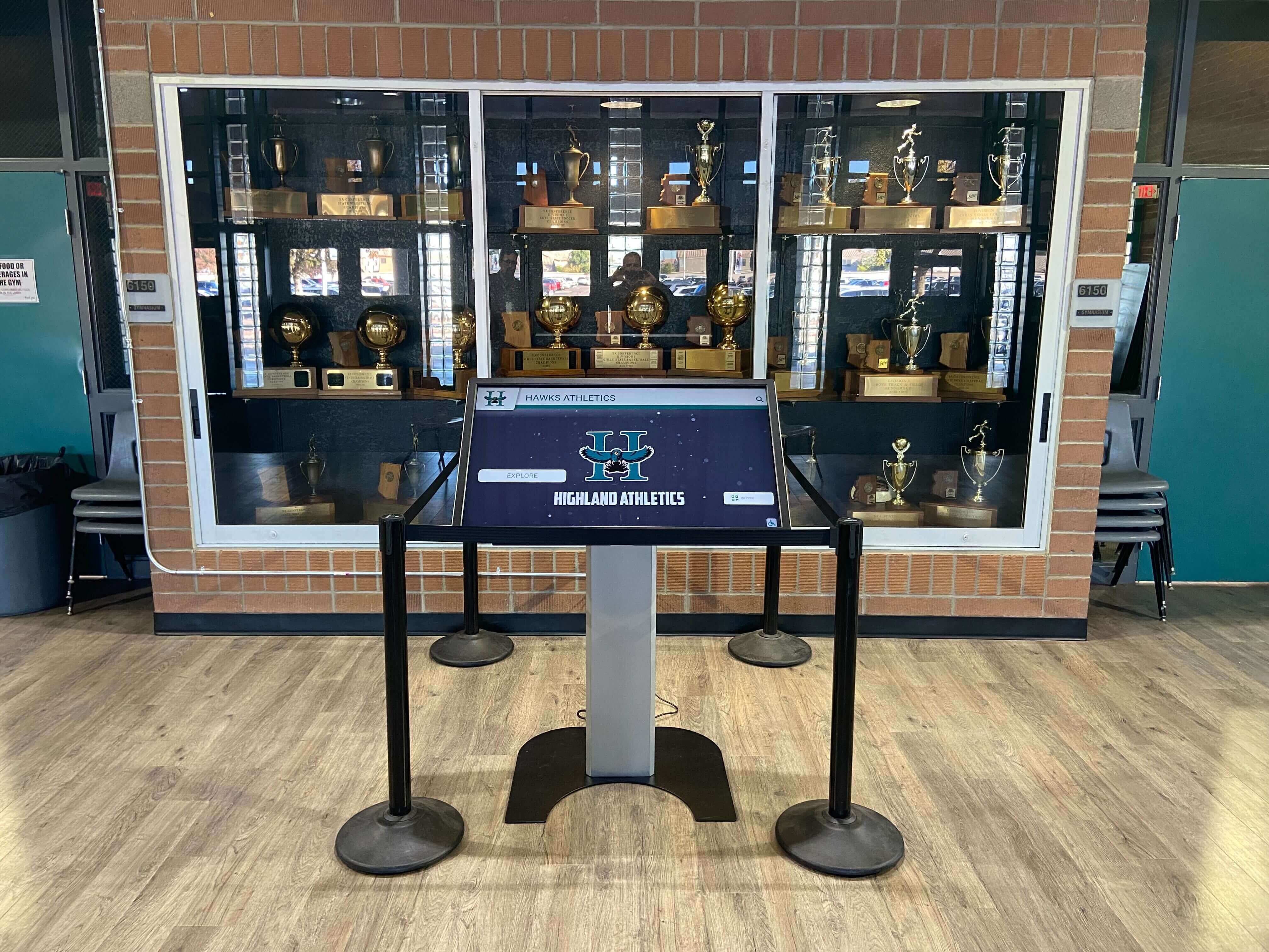
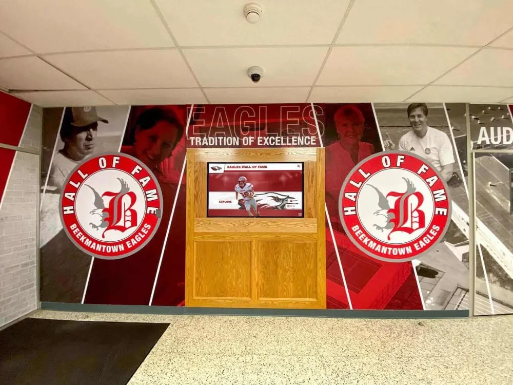
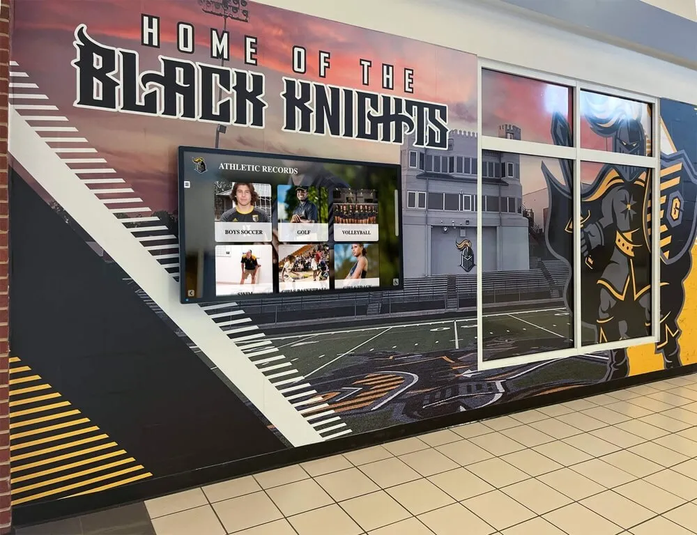
Interactive recognition kiosks in school trophy cases and athletic lobbies display footage and records drawn from legacy VHS collections — splice inspection before digitization confirms that each cassette is safe to play back, protecting both the source tape and the capture equipment from the consequences of an undetected delaminating splice
Cassette shell condition relevant to splice risk:
While examining the viewing window, also note any deformation in the cassette shell itself — cracked corners, a warped or bowed shell face, or a jammed reel hub. A cassette shell that has been dropped or subjected to heavy storage weight may have compressed the tape pack, increasing the inter-layer contact force at splice points and accelerating adhesive fatigue at those locations. A dropped cassette that shows shell impact marks near a suspected splice location warrants additional caution during the hand-wind inspection in Step 2.
Step 2: Slow Hand-Wind and Transillumination Inspection
The viewing-window inspection identifies splices visible at the tape pack edge. The slow hand-wind with transillumination detects splices whose presence is not visible from the pack edge — including splices whose splicing tape is narrower than the tape width and splices located in mid-pack layers where the edge step is obscured by the surrounding wound layers.
Equipment required:
- A pencil, rewinding tool, or a slow hand-wind peg that fits the take-up reel hub without contacting the tape strand
- A lightbox, light table, or a strong backlit surface (a tablet or monitor displaying a solid white screen at full brightness can serve as a lightbox for this purpose)
- Lint-free cotton gloves — worn throughout any tape handling to prevent skin oils from contacting the tape surface
- A magnifying loupe (5× to 10×) for adhesive-edge assessment at identified splices
Performing the slow hand-wind:
Wind the tape slowly from the supply reel to the take-up reel — one centimeter at a time, pausing to examine each exposed section of tape. As the tape crosses the lightbox or backlit surface, splicing tape appears as a transverse band of slightly reduced light transmission. The splicing tape’s adhesive and backing material absorb more light than the bare base film, making the splice location visible as a darker horizontal stripe across the tape width. A well-adhered splice with full-width splicing tape is clearly visible from both sides of the tape, appearing as a uniform darker band. A partial or offset splice — where the splicing tape does not fully bridge the joint, or was applied off-center — appears as a darker band on one side only, with a bright gap or lighter area on the opposite side where the two tape ends are unsupported.
Assessing each splice during hand-wind:
At each splice location identified during the slow hand-wind:
- Stop the wind and examine the splice area under the loupe.
- Observe the splice tape edges on both sides for any sign of lifting — the adhesive edge curling away from the tape surface, visible as a shadow line or a slight raised profile along the splice tape’s margin.
- Observe the tape surface within 5–10 mm on each side of the splice for creasing, wrinkling, or folding — a sign of stress concentration at the joint during prior playback or rewind cycles.
- Note the tape width alignment at the splice: do the two tape ends meet edge to edge, or is one end laterally offset from the other? An offset splice that places one tape end outside the nominal tape width will contact the guide posts on the misaligned side on every pass, accelerating lifting and delamination.
- Apply the lightest possible lateral pressure to the splice tape with a gloved fingertip at one edge — a fully bonded splice tape does not shift or flex. A partially delaminated splice tape shows a slight give, a visible lift, or a separating shadow at the touched edge. Do not apply enough force to initiate further delamination; this is an assessment touch, not a pressure test.
Document each splice’s position on the tape (measured from the tape start or end in minutes and seconds if a rough estimate is possible from the pack position), its type (diagonal, straight, overlap), and its assessed condition (fully adhered, partially lifting, creased zone present, fully delaminated).
Step 3: Tactile Thickness Assessment
The transillumination inspection confirms splice location and adhesive-edge condition. The tactile thickness assessment identifies splices whose optical appearance is acceptable but whose adhesive layer has shifted or softened to produce a localized thickness anomaly that would disrupt the helical-scan wrap.
With the tape passing slowly through a light pinch between a gloved thumb and forefinger — a contact gentle enough to feel thickness changes without applying lateral stress to the strand — draw the tape across the lightbox at a consistent speed. A splice tape adds a characteristic gentle bump as it passes through the gloved pinch. Note the following:
- Smooth, uniform bump: The splice tape is flat, fully adhered, and within expected thickness. The bump is brief and consistent. Continue assessment; no stop-work triggered.
- Rough or stepped bump: The splice tape edge has lifted slightly, creating an irregular leading edge as it passes through the gloved pinch. The bump feels stepped or ragged rather than smooth. Apply the stop-work evaluation in Step 4.
- Stiff, rigid section: The tape does not flex normally through the gloved contact at the splice location. Excessive rigidity indicates adhesive crystallization — an aged splice whose adhesive has dried to a glass-like hardness that no longer bonds to the tape surface uniformly and is prone to fracture under transport stress. Apply stop-work evaluation.
- Sticky residue: The tape feels tacky or the gloved fingertip shows adhesive transfer at or near the splice location. Adhesive migration — the splice tape’s adhesive bleeding onto the tape surface on either side of the joint — is a contamination risk for the head drum and guide posts. Apply stop-work evaluation.
Schools that have completed pre-digitization splice inspection and safely recovered their athletic video archive can connect that footage directly to hall-of-fame displays, lobby touchscreen kiosks, and digital recognition programs. See how Rocket Alumni Solutions connects preserved archive footage to school recognition systems that showcase program history for athletes, alumni, and community visitors.
Step 4: Stop-Work Criteria and Severity Classification
The splice inspection in Steps 1 through 3 produces a condition assessment for each splice on the cassette. Apply the following stop-work and severity framework to determine the correct disposition for each tape.
| Condition Observed | Classification | Disposition |
|---|---|---|
| Fully adhered splice, smooth edges, no creasing in adjacent tape | Pass — Low Risk | Proceed to monitored capture; note splice location in processing record |
| Fully adhered splice, smooth edges, minor wrinkle within 5 mm of joint | Caution — Borderline | Proceed with monitored capture at slow transport speed if available; log TBC use and wrinkle location |
| Lifting edge on one side of splice tape, no full delamination | Stop-Work | Do not thread; route to conservator for re-splicing evaluation |
| Lifting edge on both sides of splice tape | Stop-Work | Do not thread; route to conservator |
| Stiff or crystallized adhesive at splice | Stop-Work | Do not thread; conservator assessment required; crystallized adhesive may fracture under transport stress |
| Adhesive migration — tacky residue on tape surface within 20 mm of splice | Stop-Work | Do not thread; conservator assessment required; equipment contamination risk |
| Offset tape-end alignment at splice (ends laterally misaligned) | Stop-Work | Do not thread; guide-post contact with misaligned edge on every pass |
| Overlap splice with visible tape-end height step | Stop-Work | Do not thread; thickness step at drum entry; conservator evaluation |
| Double-spliced repair (two layers of splicing tape at one joint) | Stop-Work | Do not thread; compounded adhesive failure risk |
| Partial delamination — splice tape partially released from tape base | Stop-Work — Priority | Do not thread; route to conservator as priority; store flat in a cool, dry location |
| Full delamination — tape ends separated; splice tape floating loose | Stop-Work — Critical | Do not thread under any circumstances; store separated ends in individual archival sleeves; conservator repair required before any handling |
Stop-work does not mean the recording is lost. A cassette that triggers stop-work because of a lifting splice edge can almost certainly be re-spliced by a trained conservator using fresh, archival-grade splicing tape at the correct angle and width for the VHS format. Stop-work means that the current splice condition places the tape outside the safe-capture threshold for in-house digitization — it does not mean the footage is unrecoverable. Schools with irreplaceable recordings — a single surviving copy of a state championship game, a retirement ceremony for a long-serving coach, a final home game before a school closed — should apply the stop-work standard conservatively: any doubt about splice integrity is sufficient reason to route a historically significant cassette to a conservator before attempting capture.
Step 5: Preparing a Borderline-Pass Cassette for Monitored Capture
A cassette classified as Caution — Borderline in Step 4 has a splice that is currently adhered but shows early signs of stress that may progress during playback. The following preparation steps reduce the risk of splice failure during the capture session without requiring conservator intervention for this category.
Acclimatization: Store the cassette at room temperature (65–72°F / 18–22°C) and 40–50% relative humidity for at least 24 hours before capture. Tapes stored in cold or damp environments should not be moved directly from storage to the playback deck; condensation on the tape surface from thermal shock can introduce adhesive softening at the splice and oxide accumulation on the head drum.
Time base corrector deployment: Insert a TBC between the VHS deck output and the capture card. The TBC’s frame-synchronization function minimizes the visual impact of the brief signal disruption that occurs as the splice passes the rotating heads — the disruption is unavoidable when the splice traverses the drum contact zone, but a TBC reclocks the surrounding frames to minimize the visible artifact. This does not protect the splice from mechanical failure; it mitigates the captured signal’s quality at the splice point for the minor disruption category.
Monitored real-time capture: Do not run unmonitored capture sessions for cassettes with borderline splices. Assign a staff member to watch the capture software’s signal monitor at the time the splice is expected to reach the playback head, based on the tape-position estimate from Step 2. The monitor signal will show a brief dropout or frame disruption as the splice passes — this is expected and does not indicate mechanical failure. If the signal disruption persists beyond two or three frames, or if the transport sounds abnormal (a brief squeal, tension change, or mechanical hesitation), stop the capture immediately and assess the tape condition before continuing.
Post-capture splice documentation: After a successful capture that includes a splice pass, note the splice location in the captured file by recording the timecode at which the splice disruption is visible in the captured video. This timecode reference allows any future use of the footage — in a recognition display, a highlight compilation, or a digital yearbook clip — to be edited to avoid or acknowledge the splice artifact.
Schools managing their athletic archive cataloging under a systematic controlled vocabulary framework for archive records will find that adding a “splice location” and “splice condition at capture” field to each tape’s accession record prevents repeated investigation when cassettes are re-examined for future digitization projects or loaned to alumni and recognition program administrators.
Step 6: Escalation to a Trained Conservator and Processing Documentation
Any cassette that triggers stop-work in Step 4 must be routed to a conservator trained in magnetic tape repair before any capture attempt is made. The conservator evaluation and repair process for a delaminated or failing VHS splice typically involves the following steps, which school staff should not attempt without formal training:
Conservator re-splicing process (for reference — not a DIY guide):
- The conservator assesses the full length of tape near the failing splice under magnification to confirm that the base film has not torn, creased, or stretched in the splice area.
- The old splicing tape is carefully removed — a process that requires controlled adhesive release techniques (sometimes involving mild heat or solvent) that, if applied incorrectly, can remove oxide from the recording layer along with the old splice tape.
- The tape ends are realigned on a professional splicing block at the correct angle for VHS helical-scan geometry. For VHS, a 45-degree cut is the standard; a straight cut can be used for non-critical sections, but the 45-degree cut reduces the frame area disrupted by the splice when the joint crosses the drum contact zone.
- Fresh archival-grade splicing tape is applied — polyester-backed, pressure-sensitive, and formulated for long-term adhesion without adhesive migration — at the joint and trimmed flush with the tape edges.
- The conservator verifies the splice under magnification for edge alignment, full adhesive coverage, and freedom from bubbles or voids.
The distinction between a professional re-splice and a consumer repair attempt is not merely cosmetic. A splice applied at the wrong angle by staff using consumer splicing tape and a kitchen cutting board may pass visual inspection but will produce sync errors as it crosses the drum, leave adhesive residue on the head surface on each playback pass, and gradually peel under transport tension — converting a recoverable tape into a stop-work cassette again, now with two failed splices rather than one.
Processing documentation for all splice-inspected tapes:
Whether a cassette passes, is deferred as borderline, or triggers stop-work, the splice inspection results belong in the archive processing record.
| Processing Field | Content |
|---|---|
| Tape identifier | Accession number or unique file ID |
| Number of splices found | Total count from Steps 1–3 |
| Splice type(s) | Diagonal / straight / overlap / double-spliced / factory |
| Splice location(s) on tape | Approximate tape position (% from start, or rough time estimate) for each splice |
| Adhesive condition at each splice | Fully adhered / partially lifting / crystallized / migrating / delaminated |
| Adjacent tape condition at each splice | Clean / creased / wrinkled; distance of creasing from splice center |
| Inspection method used | Window observation / transillumination / tactile assessment |
| Classification applied | Pass / Caution–Borderline / Stop-Work (with specific stop-work criterion) |
| Disposition | Proceed to capture / deferred pending conservator evaluation / routed to conservator on [date] |
| Conservator name (if routed) | Conservator or institution |
| Post-repair re-inspection date | Date of re-inspection after conservator re-splicing |
| Capture session outcome at splice | Timecode of splice artifact in captured file, or “no artifact observed” |
| Processing operator | Name or initials |
| Inspection date | YYYY-MM-DD |
This processing record establishes a documented basis for the decision to capture the tape, defer it, or route it for repair. If a recognition program administrator or archivist reviewing the collection years later finds a frame disruption in a captured file at a specific timecode, the processing record identifies whether that disruption corresponds to a documented splice — a known and acceptable characteristic of the source material — or represents an unknown artifact requiring re-investigation.
Splice Condition Reference and Disposition Summary
| Splice Tape Condition | Visual Indicator | Tactile Indicator | Disposition |
|---|---|---|---|
| Fully adhered, edges flush | Uniform darker band under transillumination; no edge shadow | Smooth, brief thickness bump | Pass — proceed to capture |
| Fully adhered, one creased tape layer within 5 mm | Uniform band; slight shadow at crease | Smooth bump; mild stiffness near crease | Caution — monitored capture with TBC |
| Partial lifting on one edge | Edge shadow visible under loupe at one margin | Slight flex or give at touched edge | Stop-Work — conservator re-splice |
| Partial lifting on both edges | Edge shadows at both margins; splice tape slightly bowed | Flex or give at both edges | Stop-Work — conservator re-splice |
| Stiff, crystallized adhesive | Normal appearance; may show fine craze lines at 10× | Rigid, does not flex; harsh bump | Stop-Work — conservator evaluation |
| Adhesive migration | Slight gloss change on tape surface within 20 mm; adhesive islands visible | Tacky feel at touched area; glove shows residue | Stop-Work — conservator evaluation; equipment contamination risk |
| Overlap splice | Thicker band under transillumination; visible step at tape edge | Pronounced stepped bump; hard edge on one side | Stop-Work — conservator evaluation |
| Double-splice (two layers) | Double dark band or wide dark band under transillumination | Double bump; stiff through zone | Stop-Work — conservator re-splice |
| Partial delamination | Gap or lighter area at splice center under transillumination; tape ends slightly separated | Edges flex freely; center of splice tape peeling away | Stop-Work — Priority; conservator repair |
| Full delamination | Visible separation between tape ends in wound pack; splice tape loose | Tape ends slide freely; splice tape not attached | Stop-Work — Critical; do not thread; separate archival sleeving for each tape end |
The Library of Congress Sustainability of Digital Formats program recommends that archivists inspect all handling joints and adhesive splices on analog videotape before each playback session, noting that adhesive failure at splices is among the most common causes of catastrophic tape breakage during unmonitored digitization runs. The International Association of Sound and Audiovisual Archives (IASA-TC 04) identifies mechanical tape assessment — including splice identification and condition evaluation — as a mandatory pre-transfer step for any analog video preservation project.
Connecting Splice Inspection to School Athletic Recognition Programs
The athletic archive tapes that carry splices are disproportionately likely to be historically significant recordings. Coaches who spliced tapes were assembling highlight reels, joining multi-game cassettes, or repairing tapes they considered worth saving — the very categories of footage most likely to document championship seasons, long-serving coaches, and athletes whose careers a school’s recognition program would want to present.
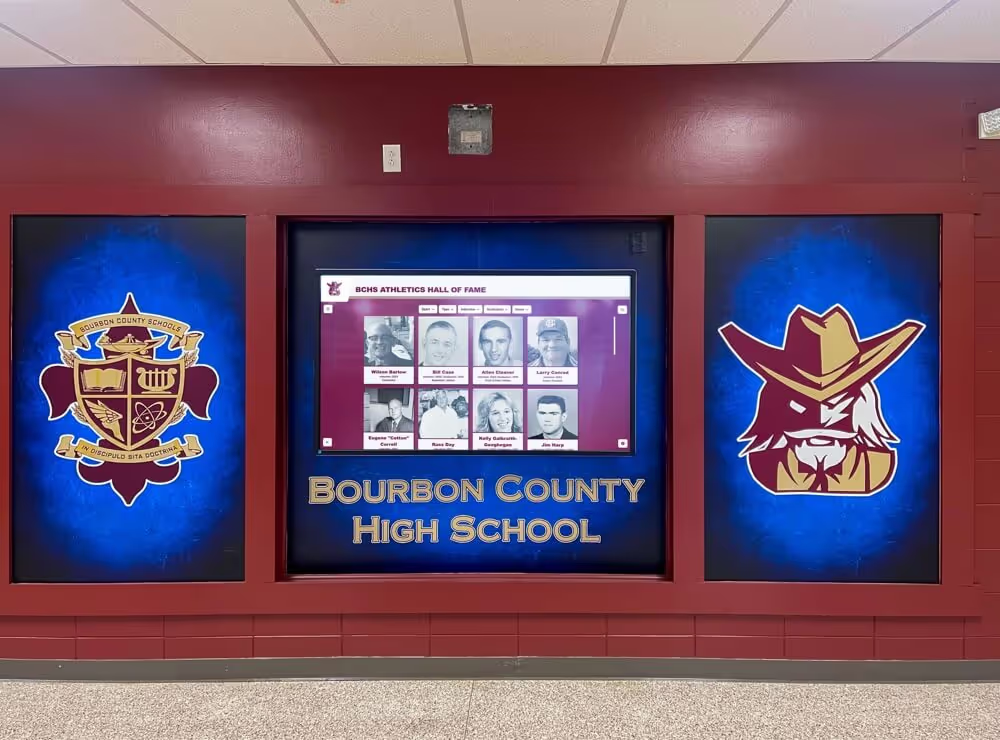
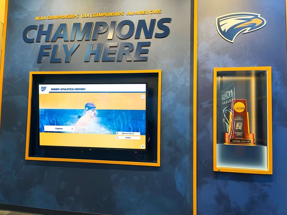
Athletic hallway recognition installations present program history alongside school identity — the video archive that supplies game footage to these systems is most valuable when its source cassettes were inspected thoroughly before capture, ensuring that the most historically significant recordings were not damaged during digitization
A splice inspection workflow transforms the decision to capture or defer from an implicit assumption — “the tape looks okay, so it will probably survive playback” — into a documented, defensible judgment based on the actual condition of each adhesive joint. For a school considering whether to invest in a digital hall-of-fame installation or an interactive recognition display built on archived footage, the difference between a complete archive and a partially captured one (with the most important tapes damaged during the first capture attempt) is the difference between a recognition program that can tell the full story and one whose most compelling moments are unavailable.
Physical archive inspection — for splices, cinching, oxide shedding, and edge damage — parallels the condition-assessment workflows applied to photographic archives in the same collections. The same systematic attention applied to assessing silver mirroring in historic team photographs before conservation treatment applies to videotape: documenting the problem before intervention, applying stop-work when the risk of further damage exceeds the risk of deferral, and routing materials that require specialist techniques to trained conservators rather than attempting repairs that exceed in-house capabilities.
The game footage that splice inspection protects is the same footage that powers the programs used to recognize athletes at awards ceremonies, communicate with alumni, and build the school community around its athletic history. Schools exploring how student-athlete recognition programs connect their athletic archive to broader school recognition will find that a systematically inspected and documented video archive provides the technical foundation those programs need to source accurate, high-quality footage for every recognition moment — from a lobby touchscreen to a banquet video tribute.
A school that has completed splice inspection, routed affected cassettes to conservators, and captured its intact recordings has a video archive that can be searched, clipped, and presented without the uncertainty that characterizes collections where tape condition was never formally assessed. The athletes and coaches documented on those tapes deserve a record that presents their performances accurately — not a record interrupted by an undetected splice failure that could have been addressed before capture began.
Schools that have built comprehensive digital archive workflows — combining pre-digitization inspection protocols with systematic digital preservation strategies that protect records across media types — position their athletic archive as a durable institutional resource rather than a collection of aging physical media waiting for an irreversible failure.
Frequently Asked Questions
Q: How do I find splices on a tape if the tape pack is tightly wound and the viewing window is small?
Use the transillumination method in Step 2. A slow hand-wind of the tape across a bright backlit surface — a dedicated light table or a tablet displaying a solid white screen at full brightness — reveals splice tape as a darker transverse band even when the tape pack edge inspection in Step 1 did not show a visible step. For a tightly wound pack where even slow hand-winding is difficult, advance the tape approximately 10 cm at a time, holding each section flat against the light surface before advancing further. This approach takes longer than a continuous slow wind but is appropriate for cassettes where the pack is tight enough that forced winding risks adding lateral stress to the strand.
Q: Can I re-splice a VHS tape in-house using consumer splicing tape rather than sending it to a conservator?
Consumer splicing tape — the narrow adhesive tape sold in hobbyist video repair kits — is not formulated for long-term adhesion and typically uses a pressure-sensitive adhesive that migrates onto the tape surface and head assembly over time. The migration deposits leave residue on the guide posts and rotating heads, reducing tracking accuracy for subsequent tapes. More critically, consumer splicing tools do not cut the tape at the 45-degree angle needed for VHS helical-scan geometry, and an incorrectly angled splice introduces sync errors at the joint on every playback. For a tape that will be digitized once and then stored, a consumer re-splice may allow a single capture session, but the adhesive migration and incorrect angle create ongoing risks for any subsequent playback. For preservation-grade archival capture of historically significant recordings, conservator re-splicing using archival-grade materials is the appropriate standard.
Q: What happens to the captured video signal when a splice passes through the head drum?
As the splice crosses the helical-scan contact zone — the section of tape in contact with the rotating drum’s heads — two conditions occur simultaneously. First, the thickness discontinuity at the splice tape changes the contact pressure between the tape and the head drum for the duration of the splice crossing. Second, if the splice involves any lateral misalignment between the two tape ends, the horizontal position of the recorded video tracks shifts by the amount of the misalignment for the frames recorded on the misaligned section. The captured video output typically shows a brief frame disruption — a horizontal sync glitch, a brief color error, or a one-to-three-frame blackout — as the splice crosses the drum. A TBC mitigates this disruption by reclocking the surrounding frames. The disruption is confined to the frames at the splice location and does not affect the rest of the captured content. Document the timecode of the splice disruption in the processing record so that future users of the footage can identify the artifact’s source.
Q: Is splice inspection necessary for S-VHS, Betacam, and U-matic tapes in the same athletic archive, or only for VHS?
The splice inspection principles in this guide — transillumination, tactile assessment, stop-work criteria for lifting adhesive — apply to any magnetic tape format that uses adhesive splicing tape for repairs. S-VHS uses the same format geometry as VHS and the same splicing technique; the workflow in this guide applies without modification. Betacam SP and U-matic use wider tape with a different helical-scan angle, but the inspection methods and stop-work criteria are identical — the different geometry changes the severity of splice-angle errors but does not change the principle that a lifting splice edge requires conservator evaluation before playback. Open-reel formats (2-inch quadruplex, 1-inch Type C) also use adhesive splicing tape and benefit from the same inspection methodology, with the additional consideration that open-reel splice angle requirements differ from cassette formats and should be confirmed against format-specific conservator guidance. Factory splices at the head and tail of any cassette format are generally low-risk but should be confirmed present and intact before threading, as a missing factory leader section on a compact format can cause the transport to contact the hub flange directly.
Q: Should splice inspection come before or after other pre-digitization checks like capstan-speed verification, edge-damage inspection, and oxide-shedding assessment?
Apply splice inspection before any playback-dependent check. Capstan-speed verification, edge-damage inspection, and oxide-shedding assessment are all performed in part during supervised playback — meaning the tape must be threaded into the deck to complete the assessment. If a cassette has a fully delaminated or critically failing splice that is not identified before threading, the first playback attempt for any purpose — including a supervised inspection playback — exposes the tape to the mechanical conditions that cause splice failure. The sequence for a comprehensive pre-digitization protocol is: (1) splice inspection, (2) cassette shell and pack inspection for cinching and edge damage, (3) Supervised playback for capstan speed and oxide shedding assessment, (4) capture with TBC. Apply the splice inspection first, route stop-work tapes to conservators before they reach Step 3, and proceed to playback-dependent checks only for cassettes that have passed or been classified as borderline-pass for splice condition.
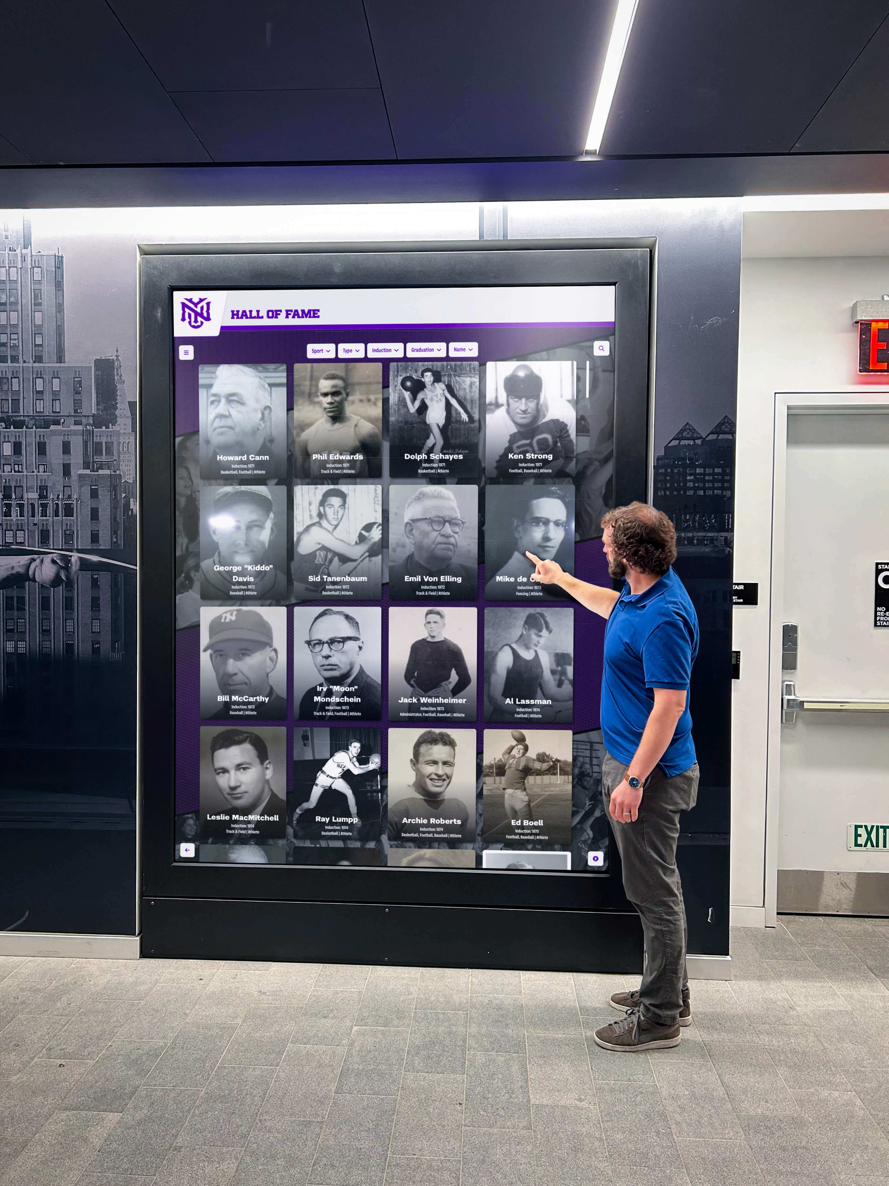
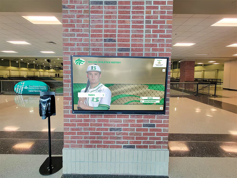
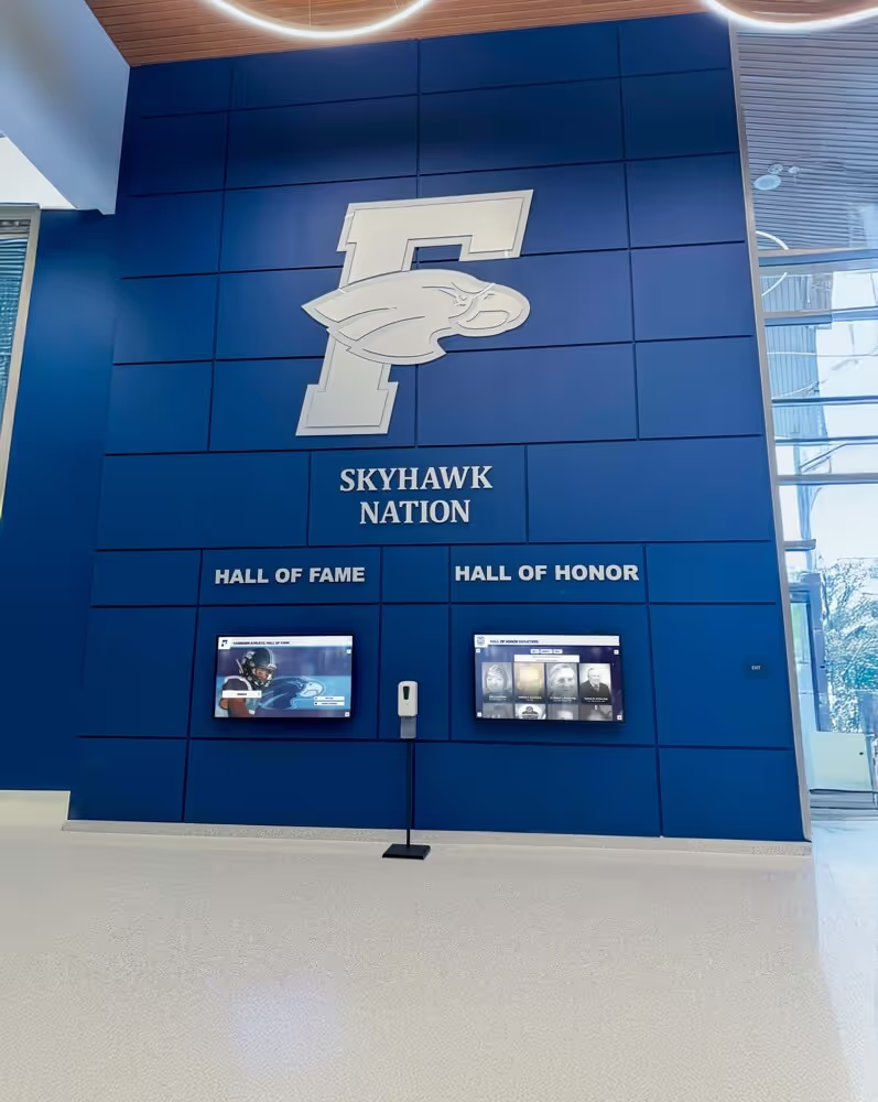
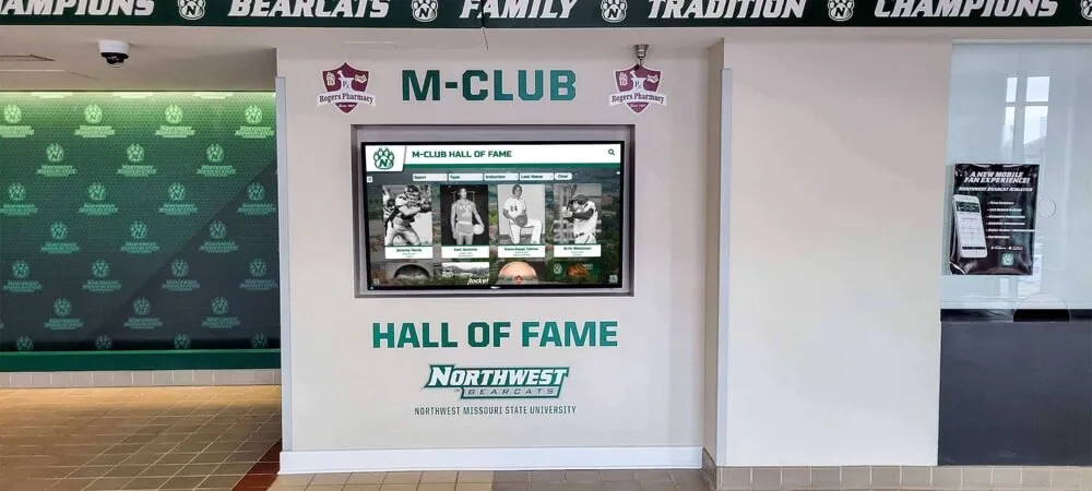
Interactive recognition displays that connect school communities to their athletic history are most effective when built on an archive whose source tapes were inspected thoroughly before capture — splice inspection is the step that confirms the mechanical integrity of each cassette before it enters the playback deck
Building Splice Inspection Into Your Pre-Digitization Protocol
The athletic archive videotape splice inspection workflow in this guide is a systematic, low-equipment process that a school archivist, AV coordinator, or athletic department volunteer can apply to an entire VHS collection using a lightbox or improvised backlit surface, a set of lint-free gloves, a 10× loupe, and the slow-wind technique described in Step 2. It does not require specialized tape analysis equipment, service-level access to the playback deck, or any modification to the cassette or tape. Its primary outputs are a splice condition assessment for each cassette and a clear, documented disposition decision — proceed, defer, or route to conservator — recorded in the archive processing file before any tape enters the playback deck.
When applied consistently at intake, splice inspection prevents the category of loss that is most avoidable and most damaging in athletic archive digitization: a capture session interrupted by a splice delamination that destroys the source recording during the very process meant to preserve it. The championship footage, tournament highlights, and coach interviews that give a school’s recognition program its depth and authenticity are frequently concentrated on the most heavily used tapes — the cassettes most likely to have been repaired with a splice. Identifying those splices before digitization begins is the step that keeps those recordings available for the recognition programs, alumni reunions, and community events where they matter most.
Ready to connect your safely preserved athletic video archive to a recognition display that gives your program’s history the presentation it deserves?
Rocket Alumni Solutions designs digital hall-of-fame systems, lobby touchscreen kiosks, and athletic recognition walls for schools — built to showcase footage from athletic archives that were preserved with care.
Request a Rocket Alumni Solutions recognition display demo →