School history, shared
Athletic Archive Video Head-Switching Noise Correction Workflow
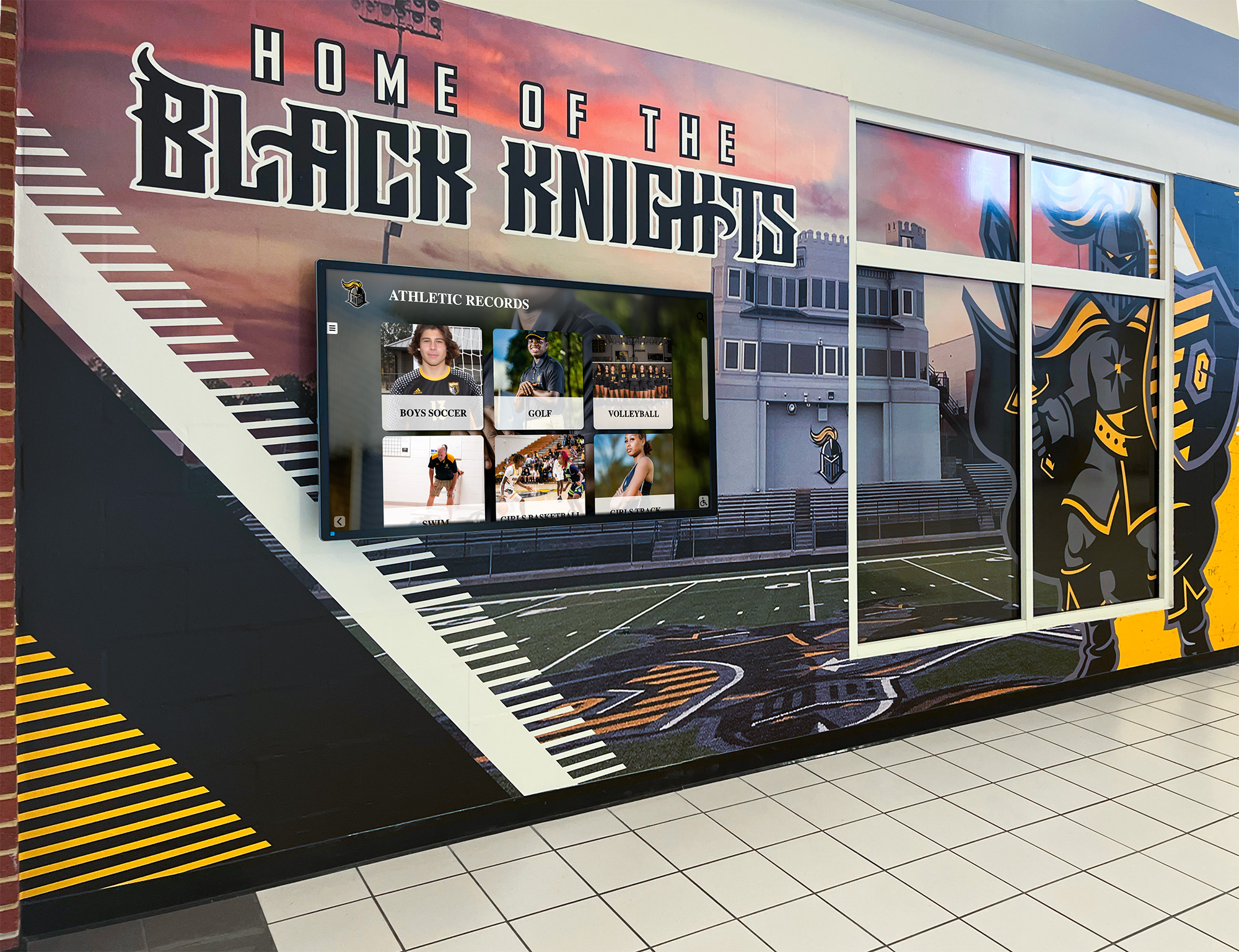
Athletic archive video head-switching noise correction is the workflow step that eliminates the horizontal band of geometric distortion and chroma noise that appears at the bottom of captured analog game footage — an artifact caused by the brief interval when a VHS or Hi8 deck’s spinning head drum transitions between its two recording heads at the end of each video field. During normal broadcast playback, a television set’s vertical blanking circuit hides these lines, so the noise never reaches the viewer’s screen. Modern digital capture hardware operating at full resolution, however, records every line the deck outputs — including the noisy head-switching interval lines that the original broadcast display would have suppressed. The result is a persistent band of visual noise, horizontal tearing, or color smearing at the very bottom of every captured frame: a defect that becomes part of the archive master and appears on every recognition display, kiosk screen, and yearbook highlight that draws from that file.
For school athletic directors, AV coordinators, IT staff, and volunteer archivists building a usable archive of game footage from the 1980s through the early 2000s, head-switching noise is one of the most common quality issues encountered during digitization — and one of the most correctable. This guide gives a step-by-step workflow for identifying the artifact, selecting the right correction approach based on the source format and available equipment, applying corrections at the capture stage or in post-processing, and documenting the outcome so that recognition programs can rely on the resulting files for hall-of-fame displays, lobby kiosks, and alumni engagement platforms.

Athletic records displays and recognition walls draw video content directly from archive master files — head-switching noise that enters the master at digitization becomes a permanent artifact visible at full scale on every screen that plays from that file
What Head-Switching Noise Is and Why It Appears in School Archive Captures
To understand head-switching noise, it helps to understand how a VHS deck’s video drum works during playback. The video drum is a spinning cylinder with two record/playback heads positioned 180 degrees apart on its surface. As the drum spins, each head sweeps diagonally across the tape, reading one complete video field — approximately 262 lines of picture information for NTSC — during each half-rotation. When one head finishes reading its field, the drum has reached the position where the second head begins reading the next field.
The instant of transition between heads — the head-switching interval — lasts for a fraction of a millisecond. During this interval, neither head is in stable contact with the tape’s recorded tracks, and the deck’s output circuit produces a momentary burst of noise, color error, or geometric distortion. In the NTSC broadcast standard, this interval was designed to fall within the vertical blanking interval: a portion of the signal between fields that television sets are built to ignore. Broadcast engineers counted on this blanking to make the head-switching noise invisible.
School game tapes were recorded on consumer and prosumer equipment calibrated to these broadcast assumptions. When the tapes are played back on the same original decks and displayed on a CRT television, the blanking works and the head-switching interval is invisible. When the same tapes are played through a modern USB capture device, an analog-to-digital converter card, or a professional capture workstation, those devices typically do not apply the same vertical blanking suppression. They capture every line the deck outputs — including the head-switching interval lines at the bottom of each field — and encode them into the archive file.
Why school athletic tape collections are particularly affected:
- Consumer VHS deck variation. Head drum timing tolerances differ between consumer deck manufacturers and even between units of the same model. A deck whose head-switching interval falls slightly outside the standard blanking window will produce noise bands that are wider or positioned higher in the frame than a well-aligned deck, making them more intrusive on capture.
- Worn playback heads. As head tips wear from repeated contact with tape oxide, the head drum may wobble or lose rotational consistency. Head wear pushes the switching interval earlier or later in the field, shifting the noise band out of the expected blanking zone and into the visible picture area.
- Mixed-era capture hardware. School archive projects often use a combination of legacy playback decks and modern capture interfaces. These combinations were not designed to work together, and the mismatch between the deck’s output timing assumptions and the capture hardware’s sampling behavior is a common source of head-switching noise visibility.
- Long-play and extended-play recordings. VHS tapes recorded in EP (six-hour) or LP (four-hour) mode use longer diagonal tracks, which changes the relationship between head drum position and vertical sync timing. Captures of EP/LP tapes frequently show wider or more prominent head-switching bands than SP-mode captures from the same deck.
The practical consequence is that a school archive digitized without head-switching noise correction will contain files where every frame carries a horizontal noise band at the bottom — typically between 4 and 16 scan lines wide — that is invisible on a standard-definition CRT television but clearly visible at 1080p on a 65-inch lobby recognition screen.
Head-Switching Noise Severity by Source Format
| Source Format | Head-Switching Noise Risk | Primary Cause | Typical Band Position | Correction Priority |
|---|---|---|---|---|
| VHS (standard play) | Moderate to High | Consumer deck timing variation; head wear common in school-use decks | Bottom 4–10 lines | High — most common format in school archives |
| VHS (EP/LP long-play) | High | Extended track geometry shifts switching interval timing | Bottom 6–16 lines; band often wider | Very high — EP/LP captures show larger bands |
| S-VHS (consumer) | Moderate | Improved deck construction, but consumer-grade timing tolerances | Bottom 4–8 lines | Moderate — evaluate per deck |
| S-VHS (professional) | Low to Moderate | Professional deck timing more consistent; internal TBC stabilizes output | Bottom 2–6 lines | Low — verify with test capture before full run |
| Hi8 / Video8 | High | Small-format head drum; timing variation common; narrow tape amplifies positional errors | Bottom 6–14 lines | High — Hi8 captures frequently require correction |
| 3/4" U-matic | Low | Professional format; stable rotary head timing; typically played on original-format decks | Bottom 2–4 lines | Low — verify at session start |
| Betacam SP | Low | Component recording and professional deck accuracy; TBC built into most decks | Bottom 2 lines or less | Very low — typically within standard blanking |
| MiniDV / Digital8 | Very low | Digital format; head switching handled internally; output is digital, not analog | Not applicable | None — digital error correction handles timing |
The formats that dominate most school athletic archives from the 1980s through the mid-2000s — consumer VHS and Hi8 — are precisely the formats at highest risk for visible head-switching noise. Any school embarking on a digitization project that includes these formats should treat head-switching noise assessment and correction as a mandatory workflow step.
Step 1: Identify Head-Switching Noise in a Test Capture
Before processing a full tape, perform a short test capture to determine whether head-switching noise is present and how severe it is. This assessment shapes the correction approach you apply to the rest of the collection.
Setting up the test capture:
- Capture a two-minute segment from the middle of a representative tape, using the full frame — do not apply any cropping, blanking, or filtering at this stage
- View the captured clip at 100% zoom in a video editor or frame viewer that lets you see the bottom of the frame clearly
- Step through the clip frame by frame for the first 30 seconds, focusing on the bottom 20 scan lines of the picture
What to look for:
Head-switching noise has a distinctive visual signature:
- A horizontal band of noise, color smearing, or geometric distortion at the very bottom of the frame, typically from the last scan line upward to roughly the 16th scan line from the bottom
- The band may appear as a wavy or bent line (horizontal sync error within the band), random pixel noise (luminance interference), or color bleeding (chroma phase error at the head-switching moment)
- The band is consistent — it appears on virtually every frame rather than appearing intermittently the way dropout does
- The band’s position is fixed within the frame; it does not shift vertically from frame to frame
Distinguishing head-switching noise from other artifacts:
Head-switching noise is distinct from:
- Dropout: appears as a white or black horizontal streak at an arbitrary position in the frame, not consistently at the bottom, and is intermittent rather than present on every frame
- Sync instability from time base error: appears as horizontal tearing or skewing distributed through the full picture, not confined to the bottom band — this is addressed by time base correction rather than head-switching correction
- Chroma noise: appears as random color grain throughout the picture, not in a fixed horizontal band at the bottom
If you see a consistent band at the bottom of every frame, head-switching noise is the cause.

Signal chain decisions at the capture workstation are permanent for the archive master — identifying and correcting head-switching noise before the file is committed to storage prevents a permanent artifact from reaching every recognition display that draws from that footage
Step 2: Hardware Approaches to Suppress Head-Switching Noise at Capture
The most effective correction for head-switching noise is prevention at the source: using hardware or capture settings that blank or suppress the head-switching interval before it is encoded into the archive file.
Time base correctors with head-switching suppression:
Many professional time base corrector units — standalone devices positioned between the playback deck and the capture card — include a head-switching suppression or “noise suppress” function. This circuit detects the timing signature of the head-switching interval and replaces the noisy lines with a black reference or with the corresponding lines from the previous field. The result is that the archive file’s bottom lines contain clean video or a stable black reference instead of noise.
If your capture workflow already includes a time base corrector, check its documentation for:
- A “head switching” or “HS suppress” control or menu option
- A “vertical sync” or “VBI suppress” setting
- A “noise suppress” or “NR” function that can be targeted to the bottom of the frame
Enable these settings on your TBC before beginning a full capture run. Some standalone TBC units used in school archive workflows — including the DataVideo TBC-1000 and TBC-3000 — include a head-switching suppression function controlled by a front-panel switch or service menu. For recognizing program-level digital hall-of-fame quality standards, ensuring the TBC is configured to suppress head-switching noise before capture is a prerequisite for archive-grade output.
Professional playback decks with better head timing:
Professional S-VHS and U-matic decks manufactured for broadcast or industrial use generally have tighter head drum timing tolerances than consumer models, and their internal timing circuits are more likely to place the head-switching interval within the standard blanking zone. If you have access to a professional-grade playback deck — such as a JVC BR-S800U or Panasonic AG-1980P for S-VHS, or a Sony BVU-950 for U-matic — using that deck rather than a consumer model often reduces or eliminates visible head-switching noise without any other intervention.
Capture software settings for vertical blanking:
Some analog-to-digital converter cards and their driver software allow you to configure the number of lines captured per field, including whether the vertical blanking interval lines are included in the output frame. Check the documentation for your capture hardware for:
- A “VBI capture” or “full resolution” setting that can be disabled
- A “blank VBI” or “suppress VBI” option that replaces those lines with black in the captured file
- A “crop bottom” setting in lines rather than pixels
Disabling VBI capture or enabling blank VBI suppression in the capture driver prevents head-switching noise from ever reaching the encoded file, which is the cleanest possible outcome. The limitation is that this approach also suppresses any useful data that might be stored in the VBI — closed caption data, time codes, or VITC — so review what VBI data your tapes contain before enabling blanking.
Step 3: Post-Capture Software Correction for Residual Head-Switching Noise
When hardware suppression is not available or does not fully eliminate the band, post-capture software correction applied to the captured file provides a second correction pass. Software correction is also the only path for files that were already captured without noise suppression and are now stored in the archive with visible artifacts.
Approach 1: Crop and reframe
The simplest software correction is cropping the bottom of the frame by the number of lines affected by head-switching noise. For a standard-definition NTSC capture (480 lines or 486 lines depending on the capture hardware), cropping the bottom 8 to 16 lines removes the noise band entirely. The trade-off is a slight reduction in frame height — the resulting file is slightly shorter than a standard-definition frame, requiring a corresponding crop from the top or an upscale to reach a standard output height.
For clips destined for recognition displays rather than broadcast, a minor reframe is typically acceptable. The noise-free picture area represents the entire portion of the image that was originally visible on a consumer television; the cropped lines are the lines that were always in the blanking zone and never seen by original viewers.
In DaVinci Resolve (free version), this correction can be applied in the Color or Cut page using the Zoom and Position controls to reframe. In VirtualDub2, a Crop filter applied to the bottom 8–16 lines achieves the same result. In AviSynth or VapourSynth, the Crop() function removes the affected lines precisely.
Approach 2: Line replacement using field data
A more sophisticated approach replaces the head-switching noise lines with corresponding lines from the previous video field rather than removing them from the frame. This technique preserves the full frame height — the archive file maintains standard-definition dimensions — while hiding the noise with the closest available picture information.
AviSynth and VapourSynth support this approach through custom scripts that detect anomalous scan lines at the bottom of the frame and substitute field-matched data. For school archives processing large volumes of similar-format tapes, a scripted line-replacement approach is more efficient than manual correction and produces consistent results across the collection.
Approach 3: Blanking the affected lines
A middle path between cropping and line replacement is replacing the head-switching noise lines with a solid black reference. This approach is used when the bottom of the frame contains no usable picture information during the affected lines anyway — as is often the case with broadcasts recorded on consumer equipment where the lower portion of the frame was outside the safe action area and showed no useful content.
Blanking does not recover any picture information, but it produces a visually clean archive file in which the noise band is replaced with a stable reference rather than unpredictable artifacts. It is also compatible with standard-definition output dimensions, unlike the simple crop approach.
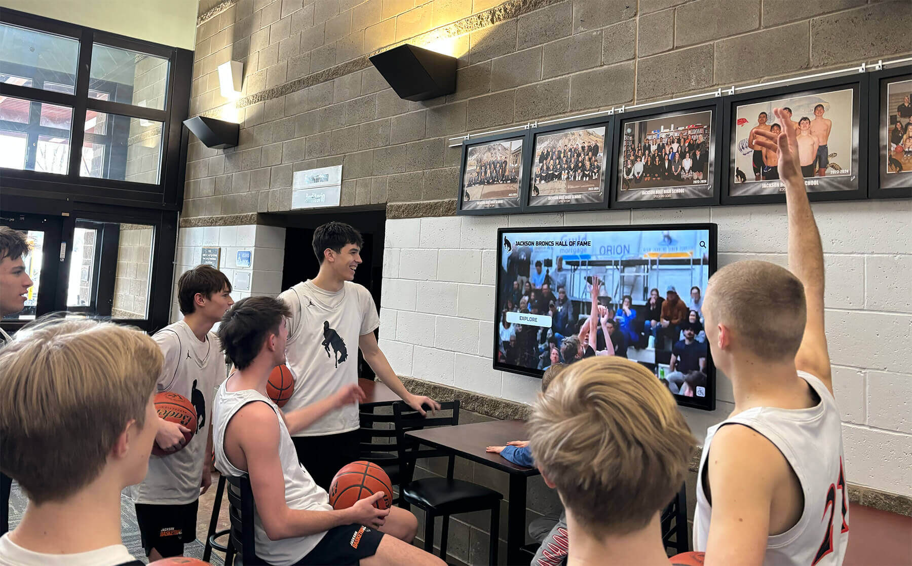
Game highlight displays in school lobbies scale archive footage to screen sizes where head-switching noise bands that were imperceptible on a small monitor become obvious horizontal distortions — correction at the archive stage prevents this artifact from reaching any display that draws from the master file
Step 4: Choosing the Right Correction Approach by Scenario
The appropriate correction method depends on how the affected files will be used, what equipment is available, and whether the source tapes can be recaptured.
| Scenario | Recommended Approach | Notes |
|---|---|---|
| New captures from existing tapes, hardware TBC available | Enable TBC head-switching suppression; configure capture driver VBI settings | Best outcome — no noise enters the archive master |
| New captures, no TBC or TBC without suppression | Use professional-grade playback deck; configure capture software to blank or crop VBI | Test capture first to verify band width before processing full collection |
| New captures, consumer VHS deck only | Capture with crop set to remove bottom 8–16 lines; apply consistent setting across collection | Document the crop setting in the capture log for future reference |
| Existing captured files with head-switching noise, original tape still available | Recapture with hardware suppression enabled | Most complete solution; justifiable for high-priority content (championships, inductions) |
| Existing captured files, original tape no longer available | Apply post-capture crop or line-replacement using AviSynth/VapourSynth or DaVinci Resolve | Software-only path for files that cannot be recaptured |
| Existing captured files, display use only (no re-export to archive master) | Apply crop at the playback or output stage in the recognition platform | Acceptable if the archive master will be used only for display, not as a source for exports |
| EP/LP-mode VHS tapes with wide noise bands | Use hardware suppression if available; crop 12–20 lines in post if not | EP/LP bands are wider; allow extra crop margin in software settings |
For a school archive that is digitizing an entire collection from scratch, establishing hardware suppression as the default at the capture stage is far more efficient than correcting noise in post-processing after the fact. For archives where some captures were completed before head-switching correction was understood as a workflow requirement, the post-capture correction approaches provide a path to upgrading existing files without requiring re-digitization of every tape.
Schools building athletic awards recognition programs around archival footage have a direct display-quality reason to prioritize head-switching correction for the game footage that appears in induction videos and trophy case displays — the content their community sees in the highest-visibility contexts.
Step 5: Integrating Head-Switching Correction Into the Full Capture Workflow
Head-switching noise correction is most effective when it is integrated as a documented step in the standard digitization workflow rather than applied reactively after noise is discovered in completed captures.
Pre-session hardware verification:
At the start of each digitization session, capture a two-minute test segment from a known-format tape and review the bottom of the frame before beginning the production run. This test:
- Confirms that the TBC’s head-switching suppression is active and effective for this specific deck-tape combination
- Establishes the band width for this session, which informs the crop or blanking settings for post-processing if hardware suppression is not fully effective
- Identifies any deck-specific timing issues — a worn deck may produce a wider band than expected, requiring an adjusted post-capture crop setting
Document the test result in the session capture log alongside the deck identifier, tape format, and TBC settings.
Workflow integration for different collection segments:
School athletic archives often contain tapes recorded across several decades on different equipment. Segment the capture schedule by format and recording era, and verify head-switching behavior for each segment before processing it in bulk:
- Pre-1990 VHS recordings: most likely to show prominent head-switching bands; prioritize hardware suppression
- 1990–2000 S-VHS or professional format: verify on representative tape before assuming lower-risk profile
- Post-2000 MiniDV or digital formats: digital output; head-switching noise is not applicable; skip to other quality checks
For schools that have invested in digital hall-of-fame touchscreen displays as part of their athletic recognition infrastructure, the practical argument for a thorough head-switching correction workflow is visible to anyone who views the display: game footage drawn from corrected archive masters looks professionally produced; footage from uncorrected captures carries an artifact that viewers associate with poor-quality preservation, regardless of the achievement the footage represents.
Step 6: Document Head-Switching Correction in the Archive Record
Thorough documentation of the correction applied to each tape ensures that future archivists and recognition program coordinators understand the provenance and processing history of each file. This documentation is particularly important for files where the original tape is no longer available for recapture.
What to record for each tape:
Create an archive intake record entry that includes:
- Tape identifier, format, and recording speed (SP, LP, or EP)
- Playback deck used (make, model, head status if known)
- Head-switching noise assessment: band width in scan lines, band position, severity description
- Correction method applied: hardware suppression (TBC model and settings), capture driver VBI settings, post-capture crop lines, or line-replacement filter details
- Software tools used, if post-capture correction was applied (tool name, version, filter settings)
- Output crop dimensions if the archive file’s frame height differs from the standard-definition capture resolution
- Final quality assessment: whether the corrected file is accepted as archive-grade or flagged for future recapture
Documenting crops in file metadata:
If post-capture cropping was applied, record the output frame dimensions in the archive file’s technical metadata. A file captured at 720×486 (full NTSC) and cropped to 720×470 to remove 16 lines of head-switching noise is not the same as a standard 720×480 output. Recognition platforms and export tools need to know the actual frame dimensions to handle the file correctly for display and export. Embedding this information as a metadata field, rather than relying on the file’s embedded stream parameters alone, supports long-term usability.
Schools that have built comprehensive recognition programs — connecting game footage to youth sports awards platforms and hall-of-fame displays — benefit from clear chain-of-custody documentation for every file in the archive. Head-switching correction records are part of that chain of custody, describing what the file contains and how it was produced.
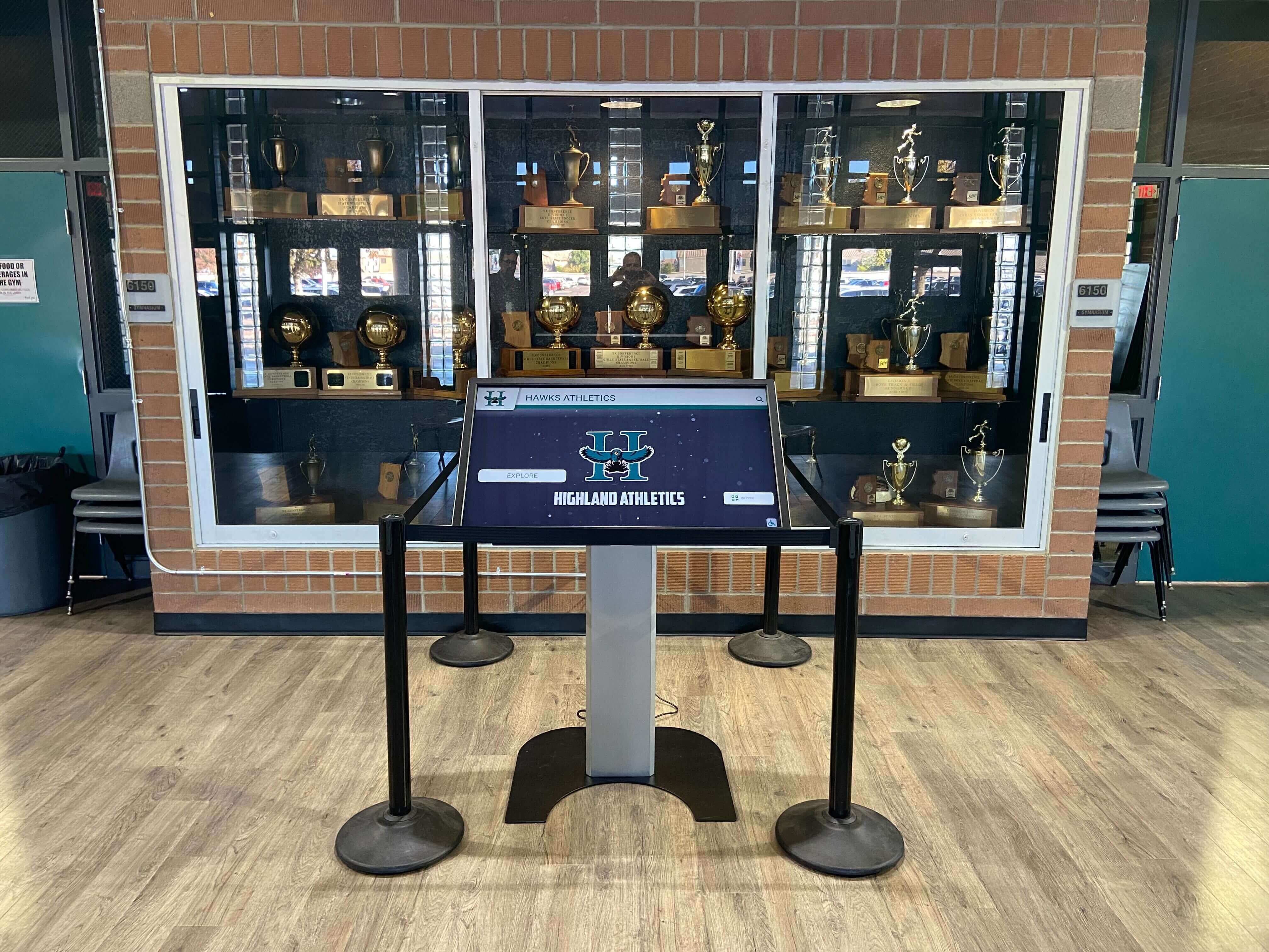
Trophy case touchscreen kiosks bring archived game footage to full display resolution in one of a school's highest-visibility spaces — head-switching noise visible at this scale undermines the professional quality of a recognition installation that was otherwise carefully designed
How Head-Switching Noise Affects Recognition Displays
The practical cost of unaddressed head-switching noise becomes clearest in the context of the recognition displays where archived game footage ultimately appears.
Recognition installations — digital hall-of-fame walls, lobby touchscreen kiosks, athletic corridor displays — present game footage at 1080p or higher resolution on screens measuring 55 inches or more. At that scale and resolution, a 10-line head-switching noise band that measured about 2 percent of the frame height on a standard-definition monitor becomes a clearly visible horizontal distortion roughly 1.5 inches tall across the full width of a 65-inch display. The band’s content — often a mix of geometric noise, color error, and a bent or shifted scan line — is visually distinctive and clearly not part of the original game footage.
For recognition programs where archived video appears alongside athlete profiles, championship statistics, and award records — the contexts where a school presents its athletic history to community members, prospective students, and alumni — this artifact is associated in viewers’ minds with poor-quality preservation. It does not diminish what happened on the field or court, but it creates a presentation mismatch between the significance of the achievement being honored and the visual quality of the evidence being shown.
Schools building display infrastructure around verified athletic recognition programs understand that display quality is part of recognition quality — a lesson that applies equally to the hardware choices for the display itself and to the archive-quality choices that determine what the display plays. Rocket Alumni Solutions, which builds digital hall-of-fame and recognition display systems for schools, depends on archive-quality source files to produce the display experience those installations are designed to deliver; head-switching noise correction in the source archive is part of what makes that possible.
Programs that use archival game footage in induction ceremonies, sports banquet highlight reels, and alumni spotlight presentations have an audience-facing reason to ensure the footage is visually clean. Community members present at these events notice visible defects in displayed footage — a detail that head-switching correction addresses before it becomes visible at a high-profile public event.
Institutions that approach vendor selection for digital recognition platforms with the same rigor they apply to archive workflows understand that the quality of the source files and the quality of the display platform are both factors in the final result. A professionally installed recognition kiosk playing video with a persistent noise band at the bottom of the frame does not look professionally installed — it looks like a quality issue that was never resolved.
Head-Switching Noise Correction Checklist
Use this checklist before beginning a capture project to ensure head-switching correction is addressed at every stage.
Pre-Capture Hardware Setup
- TBC in signal chain and configured with head-switching suppression enabled (if unit supports it)
- Capture driver reviewed for VBI capture and blanking settings
- Professional playback deck sourced where available for high-priority VHS or S-VHS content
- Deck video heads cleaned and in known working condition
- Test capture plan prepared: format, tape, two-minute segment from the middle of the tape
Per-Session Test Capture
- Test capture completed at start of each session with a representative tape from the format being processed
- Bottom 20 lines of test capture reviewed at 100% zoom, frame by frame
- Head-switching band width measured in scan lines and recorded in session log
- Hardware suppression effectiveness confirmed (band eliminated or reduced to 2 lines or fewer)
- Post-capture crop or blanking setting calculated and documented if hardware suppression is insufficient
Per-Tape Capture
- Recording speed confirmed for each tape (SP, LP, or EP) before capture begins
- TBC and capture settings verified for consistency with session baseline
- Spot-check of first 60 seconds of captured file for head-switching noise visibility
- Post-capture correction applied if residual noise remains after hardware suppression
Post-Capture Processing
- Crop, blanking, or line-replacement filter applied consistently across all tapes in the session
- Software tool, version, and filter settings logged in capture record
- Output frame dimensions recorded if different from standard capture resolution
- Corrected file reviewed at 100% zoom at the bottom of the frame in representative frames
- Audio-video synchronization verified in corrected file
Documentation
- Intake record completed with deck used, head-switching band width, and correction method
- Crop or blanking parameters documented in file metadata
- Content-critical segments noted (championship sequences, induction footage, score displays)
- SHA-256 checksum generated and recorded for each corrected archive master
- Files flagged for recapture (if original tape still available and correction was post-capture only) noted in the intake record
Frequently Asked Questions
Q: Does head-switching noise appear in every VHS capture, or only in some?
The noise is produced during every field of every VHS playback — the head-switching interval is a fundamental part of how rotating-head analog decks work. Whether it appears visibly in a capture depends on whether the capture hardware suppresses or records the interval lines. Consumer USB capture dongles frequently record the full frame including VBI lines; some professional capture cards apply blanking by default. Performing a test capture before processing a full tape collection is the only reliable way to confirm the behavior of your specific capture hardware.
Q: My captured files already show the noise band. Do I have to recapture from the original tapes to fix this?
Not necessarily. Post-capture software correction — cropping, line replacement, or blanking — can address head-switching noise in files that have already been captured. If the original tapes are still available and the affected files are high-priority content, recapture with hardware suppression will produce cleaner results than software correction alone. For files where the original tape is no longer accessible, post-capture correction is the only available path.
Q: Is head-switching noise the same thing as the “rainbow” or wavy distortion I sometimes see at the bottom of VHS captures?
The wavy, geometric distortion sometimes called the “head-switching bar” is the most common form of head-switching noise. The “rainbow” or color-smearing effect at the same location is a related artifact: during the head-switching interval, the chroma phase reference used for color decoding is also disrupted, producing color errors on the same lines where geometric distortion appears. Both symptoms have the same cause and respond to the same corrections.
Q: Our school has a mix of VHS and MiniDV tapes. Do we need head-switching correction for the MiniDV content?
No. MiniDV is a digital recording format. Its output to a capture device is transmitted as a digital signal (via FireWire/IEEE 1394) rather than as an analog composite or S-Video signal. Head-switching in a MiniDV deck is handled internally by the deck’s digital processing, and the digital output does not carry an analog head-switching noise interval. Head-switching correction is only relevant for formats that output an analog signal: VHS, S-VHS, Hi8, U-matic, and Betacam SP.
Q: Can I apply head-switching noise correction to files that are already compressed (H.264, MPEG-2)?
Post-capture software correction can be applied to compressed files, but the results are slightly degraded compared to working on a lossless or high-bitrate intraframe master. Each encode-decode cycle in a lossy codec introduces some quality loss. If your archive masters are compressed, apply any post-capture correction once and re-encode to the archive format — do not apply corrections to files that have already been corrected and re-encoded. The preferred practice is to work on lossless or high-bitrate intraframe masters during correction and produce derivative compressed files after correction is complete.
Q: How many lines should I crop to fully eliminate head-switching noise?
This varies by deck and format. Standard-play VHS from well-maintained consumer decks typically requires a crop of 8 to 12 lines from the bottom. EP-mode VHS or tapes played on decks with worn heads may require 14 to 20 lines. The correct number for your specific equipment is determined by the per-session test capture: measure the band width in your test capture at 100% zoom and set the crop margin to that width plus two lines of buffer. Document the crop setting for each session so corrections are applied consistently.

Recognition displays that highlight community heroes and athletic champions draw attention from students, parents, and visitors — the visual quality of game footage at those displays reflects the quality of the archive workflow that produced the files behind them
Building a Head-Switching-Corrected Archive for Recognition Programs
The athletic archive video head-switching noise correction workflow exists to close the gap between footage that plays acceptably on a small-screen consumer television and footage that holds up on the large, high-resolution displays where a school’s athletic history is now presented. Championship game footage, induction ceremony clips, and archival recordings of record-setting performances are not replaceable. The captures made from the original tapes are the record — and whether those captures are clean or artifact-ridden determines whether the footage can serve a recognition program with the quality it deserves.
A systematic approach — test capture before each session, hardware suppression as the primary correction, post-capture software correction for residual noise, consistent documentation — produces an archive that recognition programs can deploy with confidence. The correction work happens at digitization. Its benefit appears on every recognition screen that draws from the archive, in every induction ceremony that plays from the corrected files, and in every alumni engagement campaign that surfaces archival game footage to community members who were there when the footage was recorded.
Schools that have completed this step are positioned to connect their athletic archive to the interactive displays and touchscreen recognition platforms that make decades of game footage publicly accessible. The head-switching noise that was never visible on the original broadcast television — and was never supposed to be visible at all — should not become the artifact that defines how the school’s athletic history looks on the recognition wall.
Ready to bring your corrected athletic archive to a recognition display that does it justice?
Rocket Alumni Solutions designs digital hall-of-fame systems, touchscreen kiosks, and athletic recognition walls for schools — built to display archive-quality game footage exactly as the preservation workflow intended.
Ready to see this for your school?
Picture your collection in a custom mockup
Start with your yearbook collection and digitization goals, then request a custom digital mockup for your school.