School history, shared
Athletic Archive RF Envelope Testing: Diagnose Weak Magnetic Tape Playback Before Digitization
Athletic archive RF envelope testing is a pre-digitization diagnostic step that connects a playback deck’s radio-frequency output to a waveform monitor or oscilloscope to reveal how cleanly the deck’s spinning video heads are reading signal from the tape — before a single frame is captured to digital storage. The RF envelope is the raw, unprocessed signal that the helical-scan heads lift off the magnetic oxide coating as tape moves across them. It appears on a monitor as a wave shape whose amplitude reflects the instantaneous signal strength at every moment of playback. When head contact is good, tracking is correct, and the tape path is stable, the envelope holds a consistent high level. When any of those conditions fails, the envelope shows dips, dropouts, or oscillation — in real time, before the playback chain demodulates, error-corrects, or conceals the problem.
For school athletic directors, IT/AV coordinators, and archive staff preparing to digitize historic game broadcasts, coach interview tapes, and championship recordings, RF envelope testing answers the question that video monitoring alone cannot: is this tape playable at adequate quality right now, or does it need intervention before capture? Acting on that question before digitization avoids a range of costly outcomes — committing a degraded file to a permanent archive, damaging a deck’s video heads on an abrasive or sticky tape, or discovering unrecoverable content loss only after the tape has been played and re-shelved.
This workflow guide covers what the RF envelope reveals, how to set up the test safely, how to interpret readings, which conditions require stopping work immediately, and what fields to document so that every tape in a school’s collection carries a traceable inspection record.

Pre-digitization RF envelope testing gives AV coordinators objective evidence about tape condition before a capture session begins — protecting both the tape and the deck from a damaging or unproductive playback attempt
What an RF Envelope Reveals
Every consumer or professional analog video tape format — VHS, S-VHS, Betacam SP, 3/4" U-matic, Hi8, 8mm — uses a set of rotating video heads mounted on a spinning drum to write and read helical tracks diagonally across the tape surface. During playback, those heads skim the surface of the tape at several thousand revolutions per minute, inducing a tiny alternating electrical signal in proportion to the magnetic field strength they encounter. That signal — the RF output — is the earliest point in the signal chain where a technician can observe the raw fidelity of the read operation.
The RF envelope is specifically the amplitude of that signal over time, typically displayed on a waveform monitor with the horizontal axis representing elapsed time and the vertical axis representing signal strength. Three conditions are immediately readable from an RF envelope display.
Head Contact Quality
Good head-to-tape contact produces a high, stable envelope level close to the maximum the format’s heads are designed to deliver. Poor contact — caused by debris on the head tips, guide misalignment, warped tape, or physical deformation of the tape surface — appears as sustained low levels, rapid dips, or irregular amplitude variation. Because even partial contact loss affects the signal-to-noise ratio of the recovered video, a sustained low RF level on a tape that appears visually acceptable on a consumer monitor is often the diagnostic indicator that reveals the monitor is concealing dropout or error correction activity on every frame.
Tracking Behavior
Helical-scan video formats record information in diagonal tracks that must be precisely followed by the playback heads. When control track pulses — a separate longitudinal signal that governs head timing — are weak, erased, or off-specification, the heads cannot maintain accurate tracking of the recorded diagonal tracks. On the RF envelope, tracking problems appear as periodic level modulation: the envelope rises and falls in a rhythmic pattern as the heads alternately cross the center of the recorded tracks and drift toward the edges. On a consumer monitor with tracking circuitry, this same condition may produce only intermittent noise bands rather than a clear tracking failure, making the consumer monitor an unreliable tool for detecting the problem before it causes capture-stage errors.
Tape-Path Irregularities
The tape path — the physical route the tape takes from supply reel through guides, past the head drum, and onto the take-up reel — must hold tape tension and lateral position within tight tolerances for the heads to read correctly. Cinched tape (tape with transverse wrinkles caused by improper winding or handling), tape with deformed edges from moisture exposure, or tape stored under extreme tension can cause the tape path to shift during playback. On the RF envelope, path problems appear as lower-frequency amplitude variation: sustained dips that correspond to physical locations on the tape rather than to the per-revolution pattern of head contact events. A tape with edge damage, for example, may display a consistent level drop whenever the damaged section crosses the critical guide nearest the head drum.
Why Schools Need RF Envelope Testing Before Digitizing Athletic Archives
School athletic archives hold content that exists nowhere else: the state championship broadcast from 1988 recorded on a single VHS cassette, the open-reel coaching clinic from 1974, the Hi8 sideline interview with a coach who retired two decades ago. For content without duplicates, a degraded first-pass digitization is effectively a permanent loss — the quality captured in that session becomes the quality available to every recognition program, hall-of-fame installation, and alumni engagement initiative that draws from the archive afterward.
Consumer video monitors are not reliable diagnostic tools for magnetic tape condition because their error-concealment circuitry masks many of the conditions that degrade actual content quality. A VHS tape exhibiting moderate dropout from oxide shedding will play through a consumer TV with noise concealment active and appear marginally watchable — while the same tape’s capture file contains hundreds of concealed errors per minute that are permanently embedded in the digital record. RF envelope testing bypasses that concealment layer entirely, reporting the raw signal strength before any error correction has had a chance to hide the problem.
RF testing is also a deck protection measure. Tapes exhibiting early-stage sticky-shed syndrome or active oxide shedding can deposit binder residue and oxide particles on video head tips within seconds of playback. A head that runs across a shedding tape without prior warning can clog or abrade within the first few minutes of a session. A brief RF envelope test — 60 seconds at most on a suspect tape — gives a technician enough data to decide whether the tape needs baking, cleaning, or specialist referral before a full capture pass is attempted.
Just as a championship banner registration marks preflight review protects irreplaceable artwork before it commits to print, the RF envelope test is the pre-production quality check that protects irreplaceable athletic recordings before they enter the digitization workflow.
Safe Equipment Setup for RF Envelope Testing
RF envelope testing requires three components: a playback deck with an accessible RF test output, a display device capable of showing the RF signal, and a reference tape or tape segment of known good condition for baseline calibration.
Playback Deck Requirements
Not every deck exposes an RF test output at an accessible connector on the chassis. Professional-grade decks designed for broadcast and post-production use typically include a dedicated RF monitor output on the rear panel, labeled “RF OUT,” “ENV OUT,” or similar. Common decks used in school athletic archive digitization projects that include accessible RF outputs include:
| Deck Model | Format | RF Output Location | Notes |
|---|---|---|---|
| JVC BR-S525U / BR-S800U | S-VHS | Rear panel, BNC connector | One of the most common archival VHS decks; stable RF monitor output |
| Panasonic AG-1980 | S-VHS | Rear panel, RCA or BNC | Standard archival S-VHS deck; accessible envelope output |
| Sony BVU-950 / BVU-800 | 3/4" U-matic | Rear panel, BNC | Professional U-matic; built-in TBC and RF test point |
| Sony UVW-1800 | Betacam SP | Rear panel, BNC | Betacam SP standard; envelope output well-documented in service literature |
| Sony DSR-45 | DVCAM / DV | Internal test point | RF testing less critical for DV; primarily used for head-clog diagnosis |
For consumer VHS decks without a rear-panel RF output, some technicians access the RF signal via internal test points documented in service manuals. If your school’s digitization setup uses consumer-grade decks without accessible RF outputs, the correct response is to source a professional-grade deck before proceeding with archival capture — not to bypass the diagnostic step entirely.
Display Equipment
The RF envelope signal is a high-frequency signal that requires a dedicated display device rather than a standard video monitor:
- Waveform monitor with RF input — professional broadcast waveform monitors (Tektronix, Leader, Hamlet) designed for video production often include an RF envelope mode. This is the most readable display for staff new to RF testing because it scales automatically and includes reference lines.
- Oscilloscope — a general-purpose oscilloscope with sufficient bandwidth (5 MHz or greater) can display the RF envelope with appropriate probe and gain settings. Oscilloscopes require more configuration but are widely available and cost-effective for schools equipping a small digitization station.
- Specialized RF monitor — dedicated video RF monitors designed for tape playback environments provide the clearest envelope display, though they represent a significant equipment investment for school programs with limited archive budgets.
Establishing a Reference Level
Before testing any archive tapes, establish a reference RF level using a tape of known good condition recorded on the same format. The reference tape — ideally a test tape or a cassette known to play cleanly on this deck — tells you what a healthy RF level looks like on this specific deck-and-format combination. All subsequent readings are interpreted in relation to this reference. Without a baseline, a reading that appears “low” may simply reflect a correctly operating deck producing the format’s normal output range, rather than a tape condition problem.
The Athletic Archive RF Envelope Testing Workflow
This workflow applies to any helical-scan video format in a school athletic archive. Execute every step in order; do not advance to a later step if an earlier step indicates a stop-work condition.
Step 1: Pre-Test Head Cleaning
Before loading any archive tape, clean the video heads using a dry cotton swab or a dedicated head-cleaning cassette appropriate for the format. A head that carries residue from a previous tape session will produce artificially low RF readings on the first test tape, creating a false impression that the archive tape itself is the problem. Document the cleaning in the session log with the time and staff member’s initials.
Step 2: Load the Reference Tape and Establish Baseline
Load the reference tape. Allow the deck to reach operating temperature with the tape threaded for at least 30 seconds before observing the RF envelope. Record the stable envelope level — typically the highest sustained level the monitor displays during normal playback of the reference material — as the baseline for this session. All archive tape readings will be expressed as a percentage of this baseline figure.
Step 3: Visually Inspect the Archive Tape Before Loading
Before loading the archive tape for RF testing, conduct a brief visual inspection without opening the cassette shell:
Visual Pre-Load Inspection Checklist
- Cassette shell is intact — no cracks, separated halves, or missing screws
- Tape pack visible through cassette window appears evenly wound without cinching, warping, or gaps between layers
- No brown or reddish powder visible on internal tape or guides (oxide shedding indicator)
- No white or gray spots on tape surface visible through the window (possible mold)
- No sticky feel on tape edge at cassette opening
- No chemical or vinegar odor from the cassette
- Label and spine intact; cassette opens and closes normally on the cassette mechanism
Any cassette failing the visual check should be flagged for specialist review before loading. Do not load a cassette with visible mold, active oxide shedding, or sticky-feel indicators — those tapes require baking or cleaning by a qualified preservation lab before any playback attempt.
Step 4: Load the Archive Tape and Monitor RF for 60 Seconds
Thread the archive tape and cue to a position 30 seconds from the beginning of recorded content — not the very start of the tape, which often has physical handling wear from repeated loading over the tape’s life. Begin playback and observe the RF envelope for 60 seconds continuously. Do not exceed 60 seconds at this diagnostic stage; if the tape shows any stop-work indicator, extending playback increases head contamination risk without adding diagnostic information.
During the 60-second window, observe:
- Average envelope level relative to the reference baseline
- Consistency — does the level hold steady, or does it drift slowly or fluctuate rapidly?
- Dropout events — sudden brief drops below the envelope floor that recover within one or two frames
- Sustained low sections — prolonged drops lasting longer than a few frames
- Pattern regularity — does any amplitude variation repeat at a regular interval?
Step 5: Record Observations and Assign a Disposition
After the 60-second observation window, stop playback. Record the following measurements in the tape’s session log before making any disposition decision. Then assign one of three dispositions: proceed to capture, proceed with increased monitoring, or stop and refer for specialist evaluation. The interpretation table in the next section maps RF readings to these dispositions.

Recognition displays depend on archive quality established at the moment of capture — RF envelope testing before digitization is the checkpoint that determines whether recovered video can carry the visual and audio story a hall-of-fame display needs to tell
Interpreting RF Envelope Readings
| RF Level (% of Reference) | Consistency | Interpretation | Recommended Action |
|---|---|---|---|
| 85–100% | Stable, minimal variation | Normal playback; head contact and tracking are good | Proceed to full capture session |
| 70–84% | Minor variation, infrequent brief drops | Slightly reduced contact; possible minor oxide loss or minor head wear | Proceed with increased monitoring; flag for quality review post-capture |
| 50–69% | Moderate variation or frequent drops | Significant contact or tracking problem; possible early SSS, guide misalignment, or worn heads | Stop; clean heads and re-test; if unchanged, refer to specialist before capture |
| Below 50% | Severe variation or sustained drops | Severe head contact failure or significant tape physical problem | Stop immediately; do not proceed with capture; refer to qualified preservation lab |
| Regular oscillation pattern | Any level | Tracking problem (weak or damaged control track, head timing error) | Stop; evaluate deck tracking calibration; assess tape control track integrity |
| Sudden large drops, then partial recovery | Otherwise stable | Active oxide shedding; debris being deposited on heads | Stop immediately; clean heads; inspect tape for sticky-shed indicators |
Understanding the 70% Threshold
The 70% threshold is a practical decision point, not an absolute engineering specification. Different formats, decks, and head wear states produce different absolute RF voltage levels. What the threshold reflects is the relationship between the observed level and the reference baseline you established for that specific deck-and-format combination during this session. A tape reading at 70% of your reference baseline is sending a meaningful signal that something has changed in the signal path — head contact, tape surface condition, or physical tape geometry — that warrants attention before committing to a full capture session.
Schools using older or consumer-grade decks whose heads are already worn may see reference baselines that are inherently lower than a factory-fresh deck’s specification. In that case, the percentage-of-reference interpretation still applies: the question is not what the absolute voltage is, but whether this particular tape is deviating meaningfully from what normal playback looks like on this specific deck today.
Stop-Work Conditions
The following conditions require stopping playback immediately and removing the tape before additional playback is attempted. Continuing past any of these indicators risks head damage, oxide contamination of guides and heads, or mechanical tape damage during the playback attempt:
Stop-Work Trigger Checklist
- RF envelope level drops below 50% of reference baseline and stays low for more than a few seconds
- Rapid, large-amplitude envelope spikes followed by sudden drops (indicates oxide being ejected from the tape surface onto heads)
- Audible squealing from the tape during playback (indicates active binder shedding against the head drum)
- Visible brown or reddish residue on guides after tape is removed (confirms oxide shedding began during the test window)
- Tape fails to advance smoothly — hesitation, tight take-up reel, or deck motor audibly laboring
- Envelope shows strong regular oscillation at head-drum rotational frequency (indicates severe tracking failure with risk of tape mistrack and physical damage)
- Any unusual mechanical sound from the deck during playback (clicking, grinding, or irregular motor noise)
After a stop-work event, the deck requires immediate head cleaning with a dry cotton swab before any other tape is loaded. If oxide residue is visible on guides, clean all tape-path contact surfaces before resuming the session. Document the stop-work event in the tape record with a description of the trigger, the elapsed playback time, and the condition of guides and heads after cleaning. This documentation matters when briefing a preservation specialist: a stop-work event record tells the specialist both the nature of the problem and how much playback the tape has already experienced.
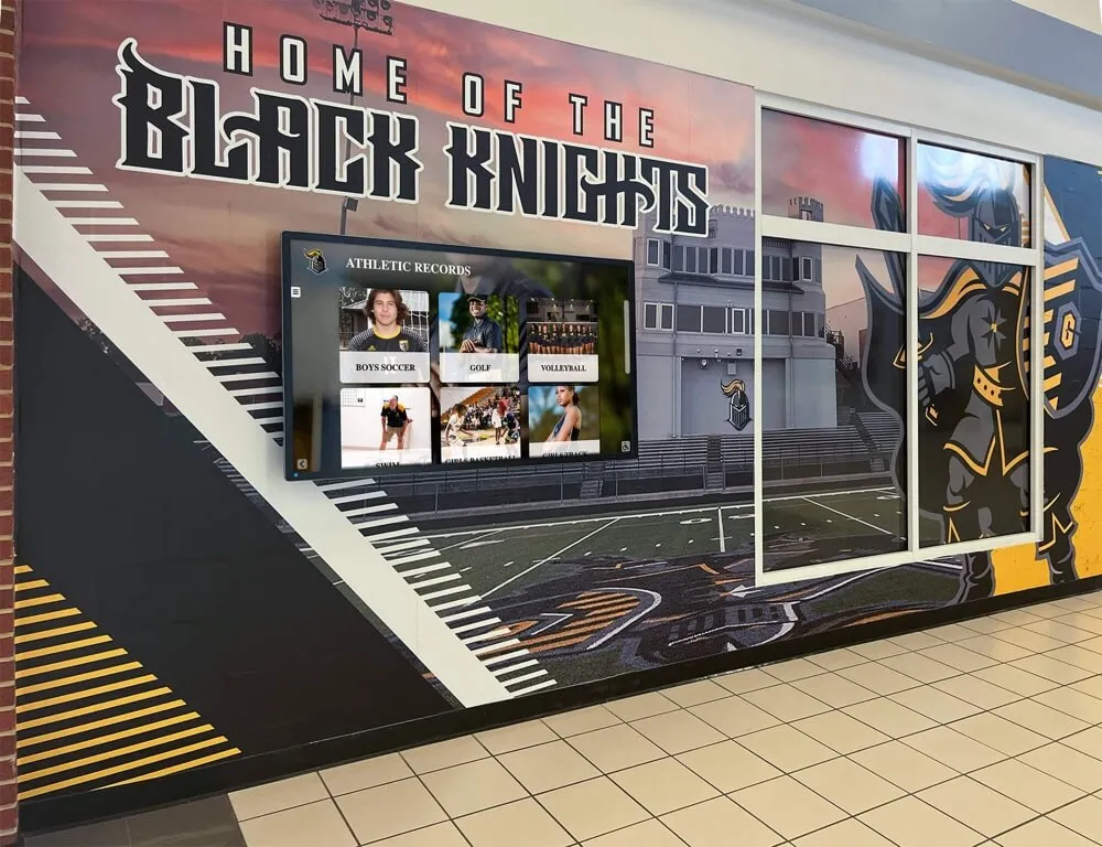
Championship records displayed in athletic hallways represent the best of a school's competitive history — RF testing before digitization protects the source recordings that power these displays from damage during the capture process
Planning a tape digitization project for your school’s athletic archive?
Rocket Alumni Solutions helps athletic departments connect recovered, high-quality digitized footage to recognition displays, digital hall-of-fame installations, and alumni engagement platforms. See what a display built from your archive could look like.
Documentation Fields for Every RF Envelope Test
Consistent documentation converts individual RF tests into a collection-level quality record that supports vendor selection, archive planning, and future re-digitization decisions. Every tape in your school’s athletic archive should carry a completed RF test record before it enters the full capture workflow. The following fields form a practical minimum for school environments:
| Field | What to Record | Example |
|---|---|---|
| Tape ID | Your archive’s unique identifier for this cassette | ATH-VHS-0142 |
| Format | Physical tape format | VHS |
| Content Label | Label text as written on cassette or box | “State Finals 1991 — Football” |
| Deck Model | Playback deck make and model | Panasonic AG-1980 |
| Head Hours (if known) | Approximate hours of use on deck heads since last replacement | 342 h (estimated) |
| Reference Level Baseline | RF level of reference tape on this deck today | 850 mV peak-to-peak |
| Observed RF Level (average) | Average RF level during the 60-second test | 680 mV pp (80% of reference) |
| Observed RF Level (minimum) | Lowest level observed during the test window | 520 mV pp (61% of reference) |
| Dropout Events | Estimated frequency of brief RF level drops | Infrequent (estimated 2–3 per minute) |
| Pattern Noted | Any regular oscillation or sustained section drop | None observed |
| Stop-Work Triggered | Yes or No; if yes, describe trigger | No |
| Test Duration | Elapsed playback time during test | 60 seconds |
| Test Date | Date of RF test | 2026-09-05 |
| Tested By | Staff name or initials | J. Reyes, AV Dept. |
| Disposition | Decision for this tape | Proceed — monitor during capture |
| Specialist Referral | If flagged, vendor name and contact | N/A |
Completed RF test records belong in the tape’s master inventory record alongside physical condition notes, format information, and content metadata. Schools using a spreadsheet-based inventory can add RF test fields as additional columns. Schools that have adopted archival management software can attach the record as a note or supplementary metadata field linked to the tape’s identifier.
Retaining RF test records from multiple sessions on the same tape is particularly valuable: a tape that tested at 80% of reference in one session and at 65% in a follow-up session two years later is showing a measurable decline in playback quality that may warrant prioritizing it for re-digitization or specialist treatment before further deterioration narrows the recovery window.
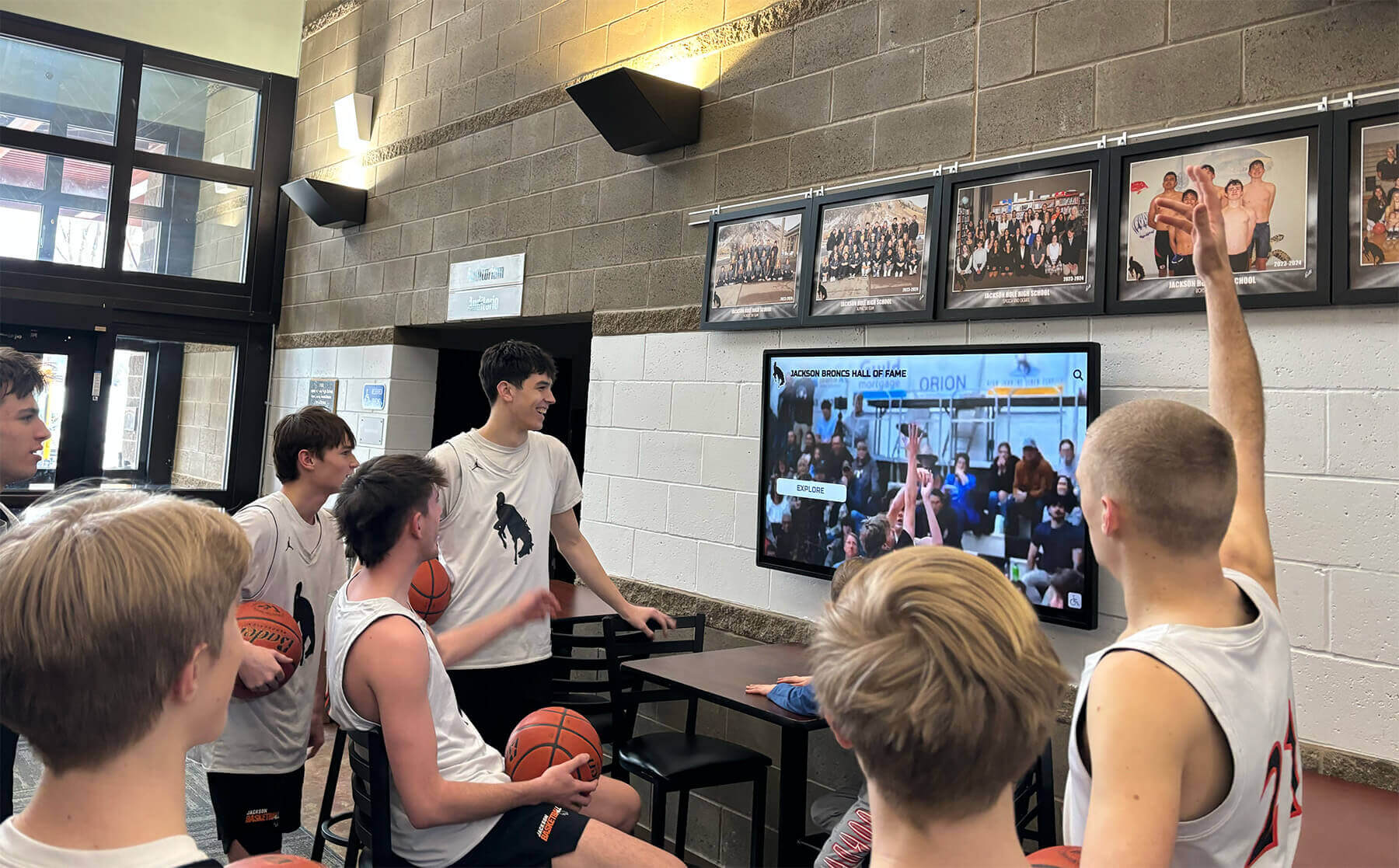
Current students accessing athletic history through school lobby displays benefit from digitization practices that protected source quality — RF envelope testing is the diagnostic checkpoint that keeps that quality chain intact from capture through display
From RF Testing to Recognition Programs
RF envelope testing is not an isolated technical exercise — it is the diagnostic foundation that determines whether a school’s historic athletic recordings can credibly support the recognition programs, hall-of-fame displays, and alumni engagement initiatives that depend on them.
Schools building digital school tour and interactive campus experiences that incorporate athletic history depend on digitized footage and audio that plays cleanly through lobby kiosks, hallway screens, and touchscreen recognition stations. An archive captured without RF pre-testing may contain hundreds of concealed dropouts per tape — errors that the digitization deck’s error-correction circuitry masked in real time but that produce visible pixelation or audio dropout when the file is decoded at a different resolution or played on a different decoder than the one used during capture.
Digital record board campus engagement programs that highlight historical athletic records alongside current-season achievements depend on video and audio material from the archive performing reliably across all display formats. A clip with a sustained RF-driven quality deficit — choppy motion, color noise, or audio dropout — cannot carry the same recognition weight as a cleanly captured clip from the same moment in program history.
Digital hall-of-fame installations that incorporate inductee highlight videos, game broadcasts, and coaching interview segments rely on archival content that was protected from the moment of capture. The RF envelope test is the earliest point in the workflow where a technician can intervene to ensure that protection is in place. Discovering playback problems after capture has occurred means either accepting lower-quality archive files or re-digitizing from the original tape — a second playback event that adds further wear to an already fragile medium.
For schools thinking about how archival media connects to long-term programs that honor athletes across generations — from letterman jacket traditions and recognition to hall-of-fame inductions — the underlying principle is the same: protecting the original record is what makes recognition meaningful years and decades later, not only in the season immediately after the achievement.
RF Testing as Part of a Broader Athletic Archive Workflow
RF envelope testing fits within a larger set of pre-digitization diagnostic steps that responsible school archive programs apply before committing any legacy tape to digital storage. It works in concert with, and comes after, physical inspection and format triage — and before capture session setup and post-capture quality control.
A complete pre-digitization workflow for school athletic video archives typically includes:
Stage 1 — Physical Triage Inspect all cassettes for sticky-shed syndrome indicators, mold, mechanical damage, and format identification. Separate tapes requiring specialist treatment from tapes safe to proceed to RF testing.
Stage 2 — RF Envelope Testing Test all physically acceptable tapes using the workflow described in this guide. Assign disposition — proceed, monitor, or refer to specialist — based on RF observations and document all findings.
Stage 3 — Deck Preparation Verify deck calibration, head condition, and transport operation before the full capture session. Confirm that the RF baseline from testing day still applies at capture day if the gap between testing and capture is longer than a week.
Stage 4 — Capture with Quality Monitoring Capture each tape while monitoring the capture signal in real time. Flag any segments showing quality events in the capture log with timestamp and description.
Stage 5 — Post-Capture Quality Review Review captured files for dropout events, audio quality, and sync integrity. Document findings and update the archive record with capture quality notes before moving the file to long-term storage.
Understanding where RF testing sits in this sequence helps allocate staff time realistically. A school planning a digitization project for 150 VHS cassettes should expect that RF testing — at 60 seconds of playback plus logging time per tape — requires two to three full working days before the capture stage begins. That investment protects every subsequent hour of capture time from the uncertainty of discovering an unplayable tape mid-session.
Booster club budget planning for archive projects often encounters the RF testing equipment question: is a dedicated waveform monitor or oscilloscope required, or can the school proceed without it? The answer depends on collection risk. Schools with collections that span the 1970s through the 1990s — the era where most of the institutional athletic memory in many programs lives — face a meaningfully higher risk of tape-related capture problems. For those collections, RF envelope testing equipment protects its cost by preventing even a single irreplaceable recording from being captured at degraded quality that cannot be corrected after the session ends.

Athlete portraits and historic video clips on touchscreen recognition displays trace their quality back to the digitization session that created them — pre-capture RF envelope testing is the step that ensures that quality is protected from the start
RF Envelope Testing: Quick-Reference Summary
What it reveals: Head contact quality, tracking accuracy, tape-path irregularities — before the consumer playback chain conceals them
Equipment needed: Professional deck with RF output (BNC), waveform monitor or oscilloscope with 5 MHz bandwidth minimum, reference tape of known good condition on the same format
Test duration per tape: 60 seconds of playback at a safe content section, plus visual inspection and logging time
Proceed threshold: Average RF at 85%+ of reference baseline, stable envelope, infrequent brief dropouts
Monitor threshold: Average RF 70–84% of reference — proceed but increase capture-stage monitoring
Stop and re-evaluate threshold: RF 50–69% of reference, moderate variation — clean heads, inspect tape, re-test before deciding
Immediate stop-work: RF below 50% of reference, audible squealing, visible oxide residue on guides after test, tape transport hesitation, or sudden large envelope spikes
Minimum documentation fields: Tape ID, deck model, reference level, observed average and minimum RF level, dropout frequency, stop-work status, disposition, date, technician name
Connecting RF-Tested Archives to Permanent Recognition Programs
Schools that complete RF envelope testing as a standard step before digitization arrive at the capture stage with something valuable: objective, documented evidence that their archive decisions are defensible. When a hall-of-fame induction video featuring 1980s game footage plays cleanly through a lobby kiosk, or a championship moment clip holds quality across many years of viewing on new display technology, that reliability traces back to the diagnostic work done before the tape was ever connected to a capture card.
The investment in diagnostic rigor before digitization also supports the broader athletic recognition infrastructure that gives an archive its long-term purpose. Schools with clean, well-documented archives can populate interactive recognition displays with video and audio that holds up to public presentation across formats — lobby screens, alumni events, hall-of-fame induction weekends, and digital yearbook segments. Schools whose archives contain degraded captures from sessions that skipped pre-digitization diagnostics find that the same recognition programs are constrained by what the archive can actually deliver.
Rocket Alumni Solutions designs and installs recognition displays built around the verified archive content that pre-digitization workflows like RF envelope testing protect. The result is recognition infrastructure with depth — programs that can surface a clearly captured 1987 state championship clip or a clean interview excerpt alongside current-season achievement data, giving alumni and current students a connected view of the program’s history that a photo-only or statistics-only archive cannot match.
Ready to turn your school’s protected athletic archive into recognition displays that honor decades of achievement?
Rocket Alumni Solutions designs and installs digital hall-of-fame displays, touchscreen recognition kiosks, and interactive athletic archive experiences for schools — built around the verified archive content that pre-digitization workflows like RF envelope testing protect.
Request a demo to see how Rocket can bring your athletic archive to life →
Ready to see this for your school?
Picture your collection in a custom mockup
Start with your yearbook collection and digitization goals, then request a custom digital mockup for your school.